


3
mouse and system interface between BNC and VGA monitors, press 0 three times on the
remote control.
NOTE: Use a BNC to RCA adapter (not included) to connect the DVR to RCA inputs (i.e. for a TV
c
onnection).
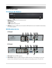
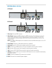
3 Audio I
nput: Input f
or 1 RCA audio-enabled camera (not included).
4 Audio Ou
tput: Output for 1 RCA audio channel (e.g. speakers).
5 VGA: Connect a VGA monitor (not included) to view the system interface.
6 LAN: Connect a CAT 5 RJ45 Ethernet cable for local and remote connectivity.
7 USB Port: Connect a USB mouse (included) or
USB flash drive (not included) for data backup
or firmware updates.
8 RS485:
Connect
compatible PTZ cameras (not included).
9 DC12V:
Connect the included AC power adapter.
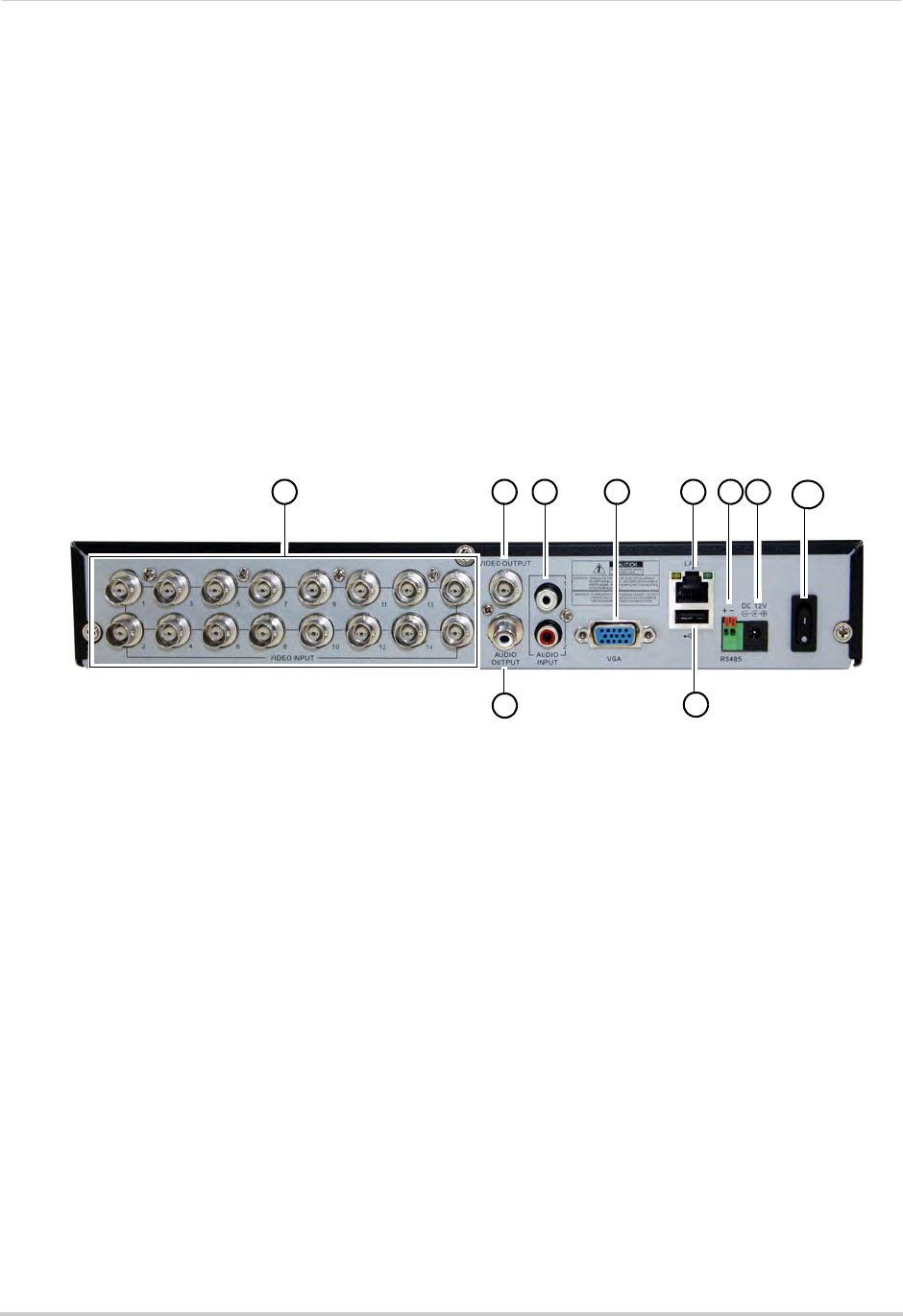
16-Channel
9
4
5
6 821
3
7
10
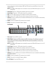
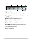
1 Video Input: Connect BNC cameras.
2 Video Output: Outputs the DVR interface to a BNC connection. This allows you to see your
mouse cursor and have full control of the system on a secondary monitor. To switch the
mouse and system interface between BNC and VGA monitors, press 0 three times on the
remote control.
NOTE: Use a BNC to RCA adapter (not included) to connect the DVR to RCA inputs (i.e. for a TV
c
onnection).
3 Audio Ou
tput: Output for 1 RCA audio channel (e.g. speakers).
4 Audio Input: Input f
or 2 RCA audio-enabled cameras (not included).
5 VGA: Connect a VGA monitor (not included) to view the system interface.
6 LAN: Connect a CAT 5 RJ45 Ethernet cable for local and remote connectivity.
7 USB Port: Connect a USB mouse (included) or
USB flash drive (not included) for data backup
or firmware updates.
8 RS485: Connect
compatible PTZ cameras (not included).
9 DC12V:
Connect the included AC power adapter.
10 On / Off Switch: T
urns the DVR on or off.