


11
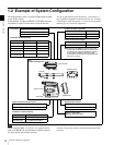
Example of System Configuration
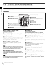
Chapter 1 Overview
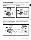
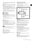
1-2-1 SRW-1 Docking System
An SRW-1 recorder can be mounted either on the top or rear of the camera head.
Power can also be supplied to the recorder via the DC IN connector (LEMO 8-pin) of the camera head.
Upper docking
The interface box can be attached to the rear.
Rear docking
The interface box can be attached to the top.
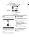
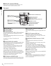
1-2-2 Optical Fiber System Using the CA-F101
Attaching an optional CA-F101 Optical Fiber Camera
Adapter to the camera enables signal transmission and
interface between the camera and the SRW-1 HD Portable
Digital Recorder/SRPC-1 HD Video Processor with the
HKSR-101 Optical Interface Unit via a hybrid optical
camera cable.
For this system, independent power supply to both the
camera and the recorder is required.
Attaching the CA-F101 to the top and the interface unit to
the rear is also allowed.
For details, refer to the Operation Manual of the CA-F101.
HDVF-C35W
Interface box
(supplied with the
camera)
DC 12 V power
SRW-1
HDVF-C35W
Interface box
(supplied with the
camera)
DC 12 V power
SRW-1
60
5.6
8
11
16
CL
2.8
2
1.6
T
ff
4
30
20
15
12
10
8
7
6
5.6
5
4.6
HDVF-C35W
Hybrid optical camera cable
DC 12 V power
DC 12 V power
SRW-1
SRPC-1 +
HKSR-101
Interface box (supplied
with the camera)
CA-F101