


14
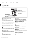
Locations and Functions of Parts
Chapter 1 Overview
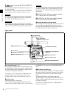
h (network) connector (RJ-45 type, 10BASE-T,
100BASE-TX)
For control from the MSU-900/950 Master Setup Unit, etc.
via a network cable.
The necessary settings are made using the NETWORK
menu displayed on the viewfinder or monitor screen.
For safety, do not connect the connector for peripheral
device wiring that might have excessive voltage to this
port. Follow the instructions for this port.
Par mesure de sécurité, ne raccordez pas le connecteur
pour le câblage de périphériques pouvant avoir une tension
excessive à ce port. Suivez les instructions pour ce port.
Aus Sicherheitsgründen nicht mit einem Peripheriegerät-
Anschluss verbinden, der zu starke Spannung für diese
Buchse haben könnte. Folgen Sie den Anweisungen für
diese Buchse.
i DC OUT 12V (DC 12V power output) connector
DC 12V power can be fed to an accessory.
j DC OUT 24V (DC 24V power output) connector
DC 24 V power can be fed to an accessory.
k Measure hook/focus reference mark
Use as reference for focusing. The same reference mark is
also provided at the right of the riser plate (page 15).
For actual measurement of the distance from a subject, you
can fix the end of a tape measure to the hook.
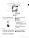
Right panel
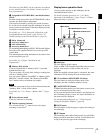
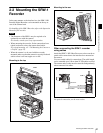
a Assignable buttons 1, 2, 3
You can assign various functions to these buttons, using
the subdisplay on the left panel or on the assistant panel or
the menu displayed on the viewfinder or monitor screen.
No function is assigned at the factory.
For details, see “3-2-11 Allocation of Functions to the
Assignable Buttons and Switch” (page 39) and “3-7
Detailed Settings of the Switch Functions” (page 54).
b LOCK switch
To disable operations on the panel.
You can make a setting to allow the RUN button to be
activated even when the LOCK switch is set to ON on the
<SUBDISPLAY 2> page on the USER (OPERATION)
menu.
c RUN button and indicator
To start/stop recording on the SRW-1 HD Portable Digital
Recorder docked on or optically connected to the camera.
The indicator is lit while the recorder is in Recording
mode.
The indicator flashes as a warning in some cases.
While the SRW-1 is operating in REC REVIEW, PLAY ,
F.FWD, or REW mode, the RUN button becomes invalid
to prevent overwriting.
For details on warning indication, see “Warning/Error
Messages” (page 126).
CAUTION
ATTENTION
VORSICHT
123
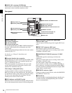
bLOCK switch
cRUN button and indicator
d4/AUTO BLK BAL switch
iMemory stick section
fAccessory clamp lever
gLock release knob
aAssignable buttons 1, 2, 3
jFocus reference mark
kTripod receptacles (bottom)
eSafety release tab
hAccessory mount lever
Display/menu operation block
(page 15)
Riser plate
Ventilation holes (intake)