


48
Viewing and Setting the Viewfinder Displays
Chapter 3 Basic Adjustments and Settings
3-6 Viewing and Setting
the Viewfinder Displays
Besides the video image, the viewfinder can display text
and messages showing the camera settings and operation
status.
The same information can be displayed on monitors
connected to the MONITOR OUT HD SDI connectors.
This information is not displayed when the camera is in
Menu Operation mode. Exit Menu Operation mode to
view the information.
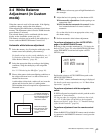
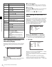
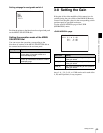
3-6-1 Viewing the Basic Status
Indications
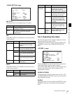
The following status indications can be superimposed on
the camera picture when you press the VF MENU/
DISPLAY button.
The display conditions can be specified on the <VF
DISPLAY> page of the USER (OPERATION) menu.
a Frame rate
The current frame rate is displayed.
b Battery indications
The conditions of output power are indicated. The left
column is for DC 12V OUT power and the right column is
for DC 24 V OUT power.
Each indication begins to flash if the corresponding input
voltage decreases to the NEAR END value specified on the
<BATT ALARM SET> page of the MAINTENANCE
menu.
Flashing becomes quicker as the voltage decreases further
toward the END value.
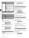
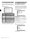
Item Selectable color-bar formats
HD-BAR (VF/
MONI)
BAR 16:9 (100%), BAR 16:9 (75%),
SMPTE 16:9 (BLACK), BAR 4:3 (100%),
BAR 4:3 (75%), SMPTE 4:3 (–I/Q),
MF-ARIB (75%), MF-ARIB (100%),
MF-ARIB (+I), MF-SMPTE (–I, Q)
SD-BAR SMPTE, EIA, FULL (EBU), 95%,
NTSC100% (PAL100%)
Note
24FPS 12.8V 24.8V
F999m CAM? T03.00
Z40
5600
W:
A TCR 00:00:00:00
1 0
dB
172.5 99M REC
12
qd
78 9
5
6
0q
a
qf
qg
qs
3
4