


15
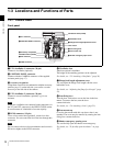
Locations and Functions of Parts
Chapter 1 Overview
The firmware of the SRW-1 may be required to be updated
for use with this camera. For details, consult your local
Sony representative.
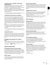
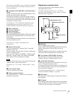
d Assignable 4/AUTO BLK BAL (auto black balance)
switch
Push the switch downward to the AUTO BLK BAL side to
start the auto black balance adjustment.
The function activated by pressing the switch upward to
the 4 side can be selected using the subdisplay on the left
panel or on the assistant panel or the menu displayed on the
viewfinder or monitor screen.
For details, see “3-2-11 Allocation of Functions to the
Assignable Buttons and Switch” (page 39) and “3-7
Detailed Settings of the Switch Functions” (page 54).
e Safety release tab
f Accessory clamp lever
g Lock release knob
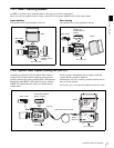
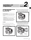
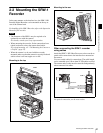
h Accessory mount lever
For mounting/unmounting an SRW-1 HD Portable Digital
Recorder or the supplied interface box to the top of the
camera head.
The mounting/unmounting mechanism is the same as that
on the rear panel (page 16).
For details, see “Chapter 2 Installation and
Preparations”.
i Memory Stick section
A slot to accommodate a “Memory Stick” is provided
behind the rubber cap.
The access lamp is lit in red while writing or reading data
to/from a “Memory Stick.”
You can use the “Memory Stick PRO” or “Memory Stick
PRO Duo” with this camera. The “Memory Stick PRO
Duo” media can be used without any adaptor.
When the access lamp is lit in red, do not insert/remove the
“Memory Stick” or turn off the camera.
For details, see “5-3-1 Using a “Memory Stick”” (page
103).
j Focus reference mark
Used as a reference for focusing.
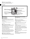
k Tripod receptacles (bottom)
Two screw holes (for
3
/
8
" camera screws) for tripod
mounting are provided.
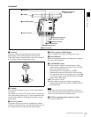
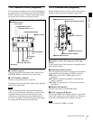
Display/menu operation block
Used to operate displays on the subdisplay and the
viewfinder/monitor screen.
For details on menu operations, see “3-2-1 Basic
Operation of the Subdisplay” (page 32) and “4-2 Basic
Menu Operations” (page 64).
a Subdisplay
For basic settings of this camera.
When an SRW-1 HD Portable Digital Recorder has been
docked, some statuses of the recorder can also be
displayed.
When the supplied assistant panel is connected, the same
information will be displayed on the assistant panel.
b VF (viewfinder) MENU/DISPLAY button
Press this button to select the display mode of the
subdisplay and the viewfinder (monitor) screen.
c CANCEL/STATUS button
In Menu Operation mode, press this button to cancel your
entry or to resume the previous status.
If you press this button when the menu is not displayed on
the viewfinder (monitor) screen, the status information of
the camera will be displayed.
For the information displayed, see “3-6 Viewing and
Setting the Viewfinder Displays” (page 48).
d PAGE button
Press this button to flip the pages or register the setting on
the subdisplay.
e SET button
The subdisplay enters Data Change mode if you hold this
button pressed for more than 1 second. Use this button also
to flip to the previous page on the subdisplay.
Note
LOCK
VF MENU/DISPLAY CANCEL/STATUS
4
AUTO
BLK
BAL
PAG E
RUN
SET
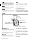
aSubdisplay
fMENU SEL/ENTER
dial
eSET button
bVF MENU/DISPLAY button
cCANCEL/STATUS button
dPAGE button