


110
Using the MSU-900/950
Appendixes
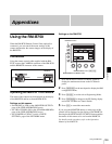
Monitoring the Camera Image
Settings on this camera
Set RM [SIG] to VBS on the <MONITOR OUTPUT>
page of the USER (OPERATION) menu.
Settings on the RM-B750
Press the MONITOR button. The camera image will be
displayed on the display of the RM-B750.
VBS signals are fed to an external monitor if connected via
the MONITOR connector of the RM-B750.
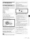
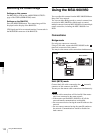
Using the MSU-900/950
You can adjust this camera from the MSU-900/950 Master
Setup Unit via a network.
You can use either Bridge mode to control a camera from
an exclusive MSU-900/950 or Multi mode to control
multiple cameras from one MSU-900/950 or from multiple
remote controllers, including the MSU-900/950 via a
HUB.
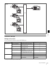
Connections
Bridge mode
For using one camera on a network.
Using a LAN cable, connect the MSU-900/950 to the
(network) connector of this camera.
You may use the remote cable connection simultaneously.
Multi (MCS) mode
Connect the LAN cable connected to the (network)
connector of this camera to the HUB.
You may use the remote cable connections simultaneously.
• Remote cable connections will be invalid if the master
unit is not connected to the same network.
• If the master-specified MSU-900/950 is off, all the
network/remote communications are disabled.
• Do not connect devices having the same IP address to the
network.
• Do not connect cameras having the same ID number to
the network. Communications would be disabled on
both cameras.
Notes
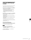
REMOTE
REMOTE
FUNCTION
MAINTE
NANCE
SCENE
PAINT
ALARM
PANEL
ACTIVE
MEMORY
STICK
STANDARDMONITORTEST BARS
5600K AUTO
KNEE
SKIN
DETAIL
BLACK
GAMMA
KNEE
SATURATION
CLOSE
AWB
AUTO
IRIS
IRIS/MB
ACTIVE
MASTER
BLACK
REMOTE CONTROL UNIT
EXT
IRIS
ABS
WHITE
BLACK
ABB
VTR
START/STOP
MSU-900/950
RM-B750
Example