


44
Setting the Camera Outputs
Chapter 3 Basic Adjustments and Settings
During adjustment
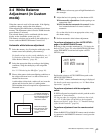
The message “AWB: EXECUTING” is displayed on the
viewfinder screen. When the adjustment process is
completed successfully, the message “AWB: OK” is
displayed.
When automatic white balance adjustment fails
If the automatic white balance adjustment process does not
end successfully, the error message “AWB: NG” will be
displayed on the viewfinder screen for approximately three
seconds.
If this error message is displayed, try white balance
adjustment again.
If the subject has a higher color temperature, use an optical
filter or set 5600K to ON, then try white balance
adjustment again.
If the error message continues to be displayed after several
attempts, the camera requires internal inspection.
If the automatic white balance adjustment is performed on
a system where the Select FPS function (see page 62) is
available, set a value that is greater than half the maximum
FPS value as the FPS value. If you do not, the error
message “AWB: LOW FPS” will be displayed, and
automatic white balance adjustment will not be available.
Example: With S23.98PsF, as the maximum FPS value is
24 FPS, set it to 13 FPS or greater before the automatic
white balance adjustment is to be performed. Although
the maximum FPS value is 50 FPS with S59.94PsF, set
it to 31 FPS or greater.
3-5 Setting the Camera
Outputs
3-5-1 Selecting a Video Output
Signal for Each Connector
The type of video signals to be output to the MONITOR
OUT HD SDI 1/2, TEST OUT, and REMOTE connectors
can be selected.
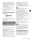
For selection, use the <MONITOR OUTPUT> page of the
USER (OPERATION) menu that is displayed on the
viewfinder screen.
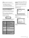
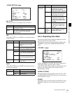
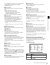
<MONITOR OUTPUT> page
COLOR
With COLOR, all R, G, and B channels will be output.
Single-channel output of R, G, or B is also possible.
SDI [SIG]
The signals to be monitored with video monitors
connected to the MONITOR OUT HD SDI 1/ 2 connectors
can be selected.
TEST [SIG]
The signals to be output to a video monitor or waveform
monitor connected via the TEST OUT connector can be
selected.
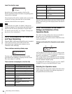
Note
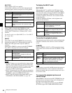
Setting Signal
MONI Regardless of the VF1/VF2 settings,
characters or the marker can be added
independently to the video output signals.
(Default)
VF1 Video signals that are output to the VF1
connector (camera images with character data
for the setting menus and status display)
VF2 Video signals that are output to the VF2
connector
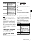
<MONITOR OUTPUT> U06
COLOR:
B
COLOR
[SIG] [SRC][MLUT]
VF : VF CAM OFF
SDI : MONI PB OFF
TEST: REFTHRU --- ---
RM : VBS CAM OFF