


17
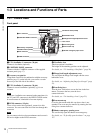
Locations and Functions of Parts
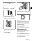
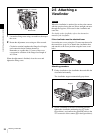
Chapter 1 Overview
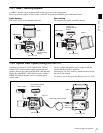
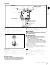
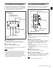
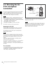
1-3-2 Assistant Panel (Supplied)
The most parts are common to those on the right panel of
the camera head. Connecting the panel to the CONTROL
PANEL connector (page 12) of the camera head permits
the camera and recorder to be operated at hand.
a CAMERA connector
Using the supplied assistant panel cable, connect to the
CONTROL PANEL connector of the camera head.
b AUX (auxiliary) connector
Connect to an external device as required.
The other parts function the same as those on the right side
panel of the camera head.
If the assistant panel cable is disconnected/connected
while you are operating the subdisplay or a menu on the
viewfinder/monitor screen, the cursor/pointer on the
subdisplay or on the menu page may inadvertently be
moved. If a ? symbol is shown on the display, first register
the setting, then disconnect/connect the cable.
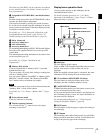
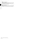
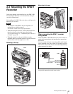
1-3-3 Interface Box (Supplied)
Being attached to the top or the rear of the camera head, it
transfers signals and power to/from the camera head.
a AUDIO IN CH-1/CH-2 connectors (XLR 3-pin,
female)
Connect audio signals. Each connector is equipped with an
input selection switch.
b Audio input selection switches
Set to the appropriate position according to the equipment
connected to the corresponding AUDIO IN connector.
LINE: When a line-level (+4 dBu) signal source is
connected
MIC: When an external microphone is connected (No
power is supplied.)
+48 V ON: To supply power of +48 V to the connected
microphone
c HD-SDI A/B connectors
For Dual Link outputs of an HD-SDI signal.
d DC IN connector (XLR 4-pin)
Connecting the BKP-L551 Battery Adaptor or a specified
power cable, supply power to the interface box. The power
is also fed to the camera head, viewfinder, and lens.
Power is not fed to an SRW-1 recorder.
Note
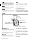
LOCK VF MENU/DISPLAY CANCEL/STATUS
4
AUTO
BLK BAL
PA G E
RUN
SET
MENU SEL/
ENTER
VF MENU/DISPLAY button
RUN button and indicator
4/AUTO BLK BAL switch
CANCEL/STATUS button
Assignable buttons 1, 2, 3
PAGE button
Subdisplay
MENU SEL/ENTER
dial
SET button
aCAMERA connector
bAUX connector
LOCK switch
Note
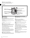
AUDIO IN
CH-2
LINE MIC
+48V ON
CH-1
LINE MIC
+48V ON
HD-SDI
A
B
cHD-SDI A/B connectors
eCamera connector 1
dDC IN connector (bottom)
aAUDIO IN CH-1/CH-2 connectors
fCamera connector 2
bAudio input selection switches