


66 Netfinity 3500-M20 – Type 8657 Models 21Y, 22Y, 31Y, 32Y,
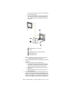
SCSI port
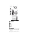
The server has an integrated dual-channel small computer
system interface (SCSI) controller. This controller supports
an Ultra160 SCSI internal channel. This channel supports
up to 15 SCSI devices. In addition, this controller uses:
• Double-transition clocking to achieve high transfer
rates
• Domain name validation to negotiate compatible data
transfer speeds with each device
• Cyclic-redundancy checking (CRC), instead of the
usual parity checking, to significantly improve data reli-
ability
• An active terminator on the system board for SCSI bus
termination
If you install a SCSI adapter in the server, you can use its
SCSI connector to connect different types of small computer
system interface (SCSI) devices.
Note: If you install a PCI RAID adapter, you can move the
SCSI cable from the system-board SCSI connector to
an internal channel connector on the RAID adapter if
you want to control the internal drives from the
adapter.
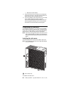
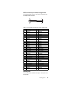
SCSI cabling requirements
You can install five internal SCSI devices using the SCSI
cable that comes with the server. If you plan to attach exter-
nal SCSI devices, you must install an optional SCSI adapter
and order additional SCSI cables. To select and order the
correct cables for use with external devices, contact your
IBM reseller or IBM marketing representative.
For information about the maximum length of SCSI cable
between the terminated ends of the cable, refer to the ANSI
SCSI standards. Adhering to these standards will help
ensure that the server operates properly.
Setting SCSI IDs
Each SCSI device connected to a SCSI controller must have
a unique SCSI ID. This ID enables the SCSI controller to
identify the device and ensure that different devices on the
same SCSI channel do not attempt to transfer data simulta-
neously. SCSI devices that are connected to different SCSI
channels can have duplicate SCSI IDs.
To install external SCSI devices, you must first install an
optional SCSI PCI adapter. Refer to the information that is
provided with the device for instructions to set its SCSI ID.
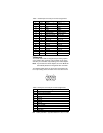
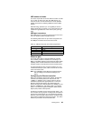
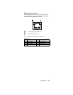
3 Ground
4+5 V dc
5Clock
6 Not connected
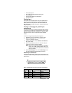
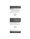
Table 10. Auxiliary-device connector pin-number
assignments
Pin Signal