


Installing options 69
USB cables and hubs
You need a 4-pin cable to connect devices to USB 1 or USB
2. If you plan to attach more than two USB devices, you
must use a hub to connect the devices. The hub provides
multiple connectors for attaching additional external USB
devices.
USB technology provides up to 12 megabits-per-second
(Mbps) speed with a maximum of 127 external devices and
a maximum signal distance of five meters (16 ft.) per seg-
ment.
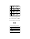
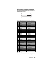
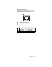
USB-port connectors
Each USB port has an external connector on the rear of the
server for attaching USB compatible devices.
The following table shows the pin-number assignments for
the USB-port connectors on the rear of the server.
Ethernet port
The server comes with an integrated Ethernet controller.
This controller provides an interface for connecting to 10-
Mbps or 100-Mbps networks and provides full-duplex (FDX)
capability, which enables simultaneous transmission and
reception of data on the Ethernet local area network (LAN).
To access the Ethernet port, connect a Category 3, 4 or 5
unshielded twisted-pair (UTP) cable to the RJ-45 connector
on the rear of the server.
Note: The 100BASE-TX Fast Ethernet standard requires
that the cabling in the network be Category 5 or
higher.
Configuring the Ethernet controller
When you connect the server to the network, the Ethernet
controller automatically detects the data-transfer rate
(10Mbps or 100Mbps) on the network and then sets the
controller to operate at the appropriate rate. That is, the
Ethernet controller will adjust to the network data rate,
whether the data rate is standard Ethernet (10BASE-T), Fast
Ethernet (100BASE-TX), half duplex (HDX), or full duplex
(FDX). The controller supports half-duplex (HDX) and full-
duplex (FDX) modes at both speeds.
The Ethernet controller is a PCI Plug and Play device. You
do not need to set any jumpers or configure the controller for
the operating system before you use the Ethernet controller.
However, you must install a device driver to enable the oper-
ating system to address the Ethernet controller. The device
drivers are provided on the ServerGuide CDs.
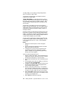
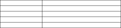
Table 13. USB-port connector pin-number assignments
Pin Signal
1VCC
2-Data
3+Data
4Ground