


1-11
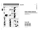
DXC-D30WS/P(E)/V1
Chapter 1 Overview
8
Chapter 1 Overview
Features
2
/
3
-inch IT type Power HAD CCD
The DXC-D30/D30P Color Video Camera uses
2
/
3
-
inch IT type Power HAD CCDs. It outperforms most
of the exiting FIT type CCD cameras for high-end use,
in both picture quality and sensitivity.
•Smear: –125 dB
•Sensitivity: F11.0 (at 3200 K, 2000 lux)
•S/N: 63 dB (DXC-D30) or 61 dB (DXC-D30P)
Sophisticated image processing
TruEye™ processing makes possible the following
performance features. This new digital signal
processing has brought reproduction of natural colors
to the level achieved by the human eye.
DynaLatitude™
Enables detailed adjustment of contrast control in each
pixel in accordance with a histogram of luminance
signal levels.
DCC+ (dynamic contrast control plus)
Prevents white breakup when shooting a high intensity
subject, and also prevents color faults in high intensity
subject.
Black stretch and compress
Enables control of luminance signal levels in black
areas without changing the hue.
Variety of detail corrections
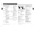
•Skin detail function: this function gives a slightly
softer appearance to the subject’s face. The target
skin color can be automatically set.
•Black halo correction
•Red/green vertical detail correction: this function
performs vertical detail compensation for both red
and green signals.
•Horizontal detail frequency control
Recording and managing setup data
In addition to the setup menu that is displayed in the
viewfinder screen, the DXC-D30/D30P is equipped
with the following functions to facilitate camera head
setup.
Setup file system
You can use setup files when making adjustments or
settings. The DXC-D30/D30P comes with factory
preset files that contain shipped settings and you can
freely create user files as well.
Automatic recording of setup data (when
using DSR-1/1P)
When the DXC-D30/D30P is connected to the DSR-1/
1P VTR, two types of setup data can be recorded.
SetupLog™: Shooting-related environment settings
are recorded onto the tape at intervals of a few
seconds. This recorded data can then be used to
reproduce the same shooting conditions in
subsequent shots. It also makes it easier to
identify the causes of problems in previous shots.
SetupNavi™: The setup conditions selected with the
setup menu and setup files are recorded onto the
tape. The recorded setup data can be copied to
other camera heads so that the same setup can be
shared among several camera heads.
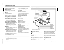
ClipLink™ Function (when using DSR-
1/1P)
The ClipLink function can be used at every step from
acquisition to editing. Information necessary for
editing is recorded when shooting to ensure fast and
efficient editing operations.
When you set a recording start (Rec IN) point or when
you press the TAKE button to set a Mark IN point, the
video image at that point is recorded on the tape in
compressed form as an Index Picture. In addition, the
time codes for such editing points (Mark IN/Mark
OUT points or cue points) are recorded along with
other editing point data (such as the cassette number
and scene number) into cassette memory (as ClipLink
log data). Unsuccessful scenes containing faults can
also be marked in cassette memory as “NG”, so that
only the good scenes are taken up from cassette
memory when editing.
Chapter 1 Overview
Chapter 1 Overview
9
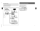
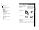
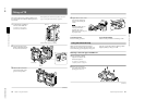
Dockable with various types of VTRs
The DXC-D30/D30P docks with the DSR-1/1P
DVCAM VTR to configure the DSR-130/130P digital
camcorder. It also docks with the PVV-3/3P Betacam
SP VTR to configure the PVW-D30/D30P Betacam SP
camcorder. In addition, the DXC-D30/D30P docks
with the EVV-9000/9000P Hi-8 VTR. Using an
adaptor (not supplied), it is also able to dock with a
variety of existing S-VHS VTRs.
New Functions boost operability
EZ (easy) mode function
When there isn’t time to check the camera head
settings, simply press the EZ mode button to start the
auto adjustment function using standard settings.
There is no need to lose a shot for lack of setup time.
EZ (easy) focus
Press the EZ focus button before shooting to ensure a
quick and accurate focus.
Programmable gain
The amount of gain relative to the GAIN switch setting
(H, M, or L) can be programmed as –3 dB, 0 dB, 3
dB, 6 dB, 9 dB, 12 dB, 18 dB, 18 dB+DPR
1)
, 24 dB,
24 dB+DPR and hyper gain.
Hyper gain
Hyper gain (36 dB, or about 60 times greater than
0 dB) can be easily set via one switch setting. This can
also be done from remote equipment.
Auto tracing white balance
This function automatically traces the white balance,
which constantly changes as lighting conditions
change. Auto tracing white balance is especially
useful when there is no time to manually adjust the
white balance or when shooting moves between indoor
and outdoor locations.
Intensified auto iris control
In addition to the standard auto iris, the intelligent auto
iris function adjusts the lens iris to compensate back
lighting or spot lighting.
Total level control system (TLCS)
Even if the incoming light exceeds the range in which
the standard auto iris can control exposure, the auto
gain control (AGC) or auto exposure (AE) backs up to
ensure proper exposure.
Dual pixel readout (DPR)
When the gain is set to either 18 dB or 24 dB, the gain
setting can be doubled (6 dB up) without increasing
the noise level.
Recording time display
Recording time can be displayed in either of the
following modes.
•Total recording time for all cuts
•Total recording time for current cut
Viewfinder super detail
Video signals for the viewfinder are mixed with V-
DTL signals to make focusing easier.
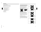
Dual zebra pattern display
Two types of zebra patterns, zebra 1 and zebra 2 can
be displayed simultaneously or independently. The
zebra 1 can be set to the levels ranging from 70 to 90
IRE on the DXC-D30 (or from 70 to 90% on the DXC-
D30P) and the zebra 2 indicates the levels of 100 IRE
for the DXC-D30 or more (or the levels of 100% or
more for the DXC-D30P).
Color temperature display
When reading the white balance, the color temperature
is displayed on the viewfinder screen.
Video monitor output with text
The video signal with text superimposed that is shown
in the viewfinder can also be output to an external
video monitor.
Camera head microphone output indicator
An indication ≥ appears in the viewfinder whenever a
signal is being output from the camera head’s
microphone.
1-kHz reference signal output
Along with a color bar, a 1-kHz reference signal can
also be output.
..........................................................................................................................................................................................................
1) DPR = Dual Pixel Readout