


3-6
DXC-D30WS/P(E)/V1
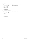
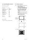
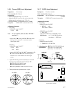
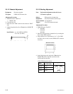
3-3-5. Carrier Balance Adjustment
Equipment: Verctorscope (MAX GAIN)
Preparation: OUTPUT/DL/DCC+ switch/camera side
→ BARS
Test point: VIDEO OUT connector/camera side
Adjusting point:
1. SERVICE menu “PAGE 7”
→ R-Y C/B :
B-Y C/B :
2. Move the cursor to R-Y C/B or B-Y C/B with
STATUS/MENU switch, and adjust the UP 4 switch or
DOWN $ switch so that the beam spot is in the center
of the vectorscope.
R
M
G
C
Y
G
Y
L
B
R
M
G
C
Y
G
Y
L
B
75%
100%
75%
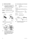
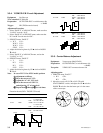
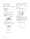
3-3-4. Y/SYNC/R-Y/B-Y Level Adjustment
Equipment: Oscilloscope
To be extended: IF-700 board
Preparation: OUTPUT/DL/DCC+ switch/camera side
→ BARS
Trigger: HD (TP83/extension board)
Adjustment Procedure:
1. Select “PAGE 9” of ADVANCE menu, make sure that
“16:9/4:3” must be “16:9”.
2. Select “PAGE 10” of SERVICE menu, make sure that
R-Y and B-Y mode must be “ON”.
3. SERVICE menu “PAGE 5”
→ W Y LVL :
W R-Y LVL :
W B-Y LVL :
SYNC LVL :
4. Adjust the following items by UP 4 witch or DOWN
$ switch.
5. Select “PAGE 9” of ADVANCE menu, and set the
“16:9/4:3” to “4:3”.
6. SERVICE menu “PAGE 5”
→ Y LVL :
R-Y LVL :
B-Y LVL :
S-UP LVL :
7. Adjust the following items by UP 4 witch or DOWN
$ switch.
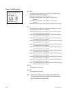
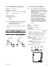
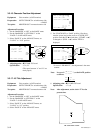
Note: In case of Y LVL for NTSC model, perform
the adjustment as follows.
11
11
1 Move the cursor to Y LVL.
22
22
2 Adjust the “A” of Y LVL level.
33
33
3 Move the cursor to S-UP LVL,
and adjust the “F” of setup level.
44
44
4 Repeat item
11
11
1 through
33
33
3 several times.
Extension board (GND : TP63/IF-532 board)
Item Test Point Specification
W Y LVL TP61 NTSC : A = 714 ±10 mV
F = 54 ±5 mV
PAL : A = 700 ±10 mV
Y LVL TP61 NTSC : A = 714 ±10 mV
F = 54 ±5 mV
PAL : A = 700 ±10 mV
SYNC LVL TP61 NTSC : B = 286 ±5 mV
PAL : B = 300 ±5 mV
C
D
B
A
(NTSC) (PAL)
B
A
F
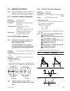
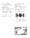
W R-Y LVL TP60 NTSC : 700 ±20 mV
PAL : 525 ±20 mV
R-Y LVL TP60 NTSC : 700 ±20 mV
PAL : 525 ±20 mV
W B-Y LVL TP62 NTSC : 700 ±20 mV
PAL : 525 ±20 mV
B-Y LVL TP62 NTSC : 700 ±20 mV
PAL : 525 ±20 mV