


1-30
DXC-D30WS/P(E)/V1
46
Chapter 4 Viewfinder Screen Indications and Menus
Chapter 4 Viewfinder Screen Indications and Menus
PAGE 1(NEXTm$ PREVm4)
mALL RESET
(YESm4)
EXIT MENU (YESm4)
PAGE 1(NEXTm$ PREVm4)
mALL RESET SURE?
(NOm$ YESm4)
EXIT MENU (YESm4)
PAGE 2(NEXTm$ PREVm4)
GAIN
mHIGH:18dB
MID: 9dB
LOW: OdB
DL:ON
EXIT MENU (YESm4)
PAGE 3(NEXTm$ PREVm4)
mAWB MEM:2
TONE:OFF
BARS:SMPTE
REMOTE1:REC
REMOTE2:MARK
BAUD RATE:9600
EXIT MENU (YESm4)
PAGE14(NEXTm$ PREVm4)
SETUP NAVI
CAMERAmTAPE
mSTORE DATA
(YESm4)
EXIT MENU (YESm4)
TCG 2:34 56:1:00
ND
08 4429
224MP
S1/00:0S1
189
:
M
0
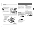
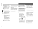
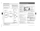
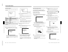
Displaying the advanced menu and
switching to the normal indications
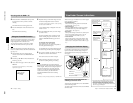
Use the following procedure to display the advanced
menu.
1 Move the POWER switch to the ON position while
holding down the UP/ON button to display the
advanced menu selection screen.
2 •To display advanced menu page 2
immediately, move the cursor to the menu
number and then press the DOWN/OFF button.
•To reinitialize all settings in the advanced
menu to their factory defaults, press the UP/ON
button. A confirmation screen appears. Press the
UP/ON button to confirm the reinitialization, or
the DOWN/OFF button to cancel it. In either
case, the display now switches to advanced menu
page 2.
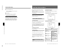
Viewfinder Screen Indications
a) Set the cursor to the page number and press the UP/ON or
DOWN/OFF button.
b) The menu configuration differs according the camera head’s
switch settings, the connected VTR, and the type of input
signal. A 14-page configuration results when all of the
advanced menu pages are displayed.
c) Set the cursor to EXIT MENU and press the UP/ON button.
Move the POWER switch to the
ON position with the UP/ON
button held down
UP/ON button
a)
Pressing the MENU/
STATUS switch down
Confirmation
screen
UP/ON button
a)
DOWN/OFF button
a)
DOWN/OFF
button
DOWN/OFF button
UP/ON
button
c)
No
reinitalization
All settings in the
advanced menus
reinitialized
Normal indications
UP/ON
button
c)
UP/ON or DOWN/
OFF button
a)
page 3
page 2
page 14
b)
UP/ON button
c)
DOWN/OFF button
a)
UP/ON or DOWN/
OFF button
a)
Advanced menu
page 1
UP/ON
button
a)
Chapter 4 Viewfinder Screen Indications and Menus
47
Chapter 4 Viewfinder Screen Indications and Menus
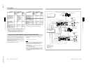
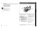
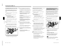
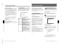
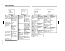
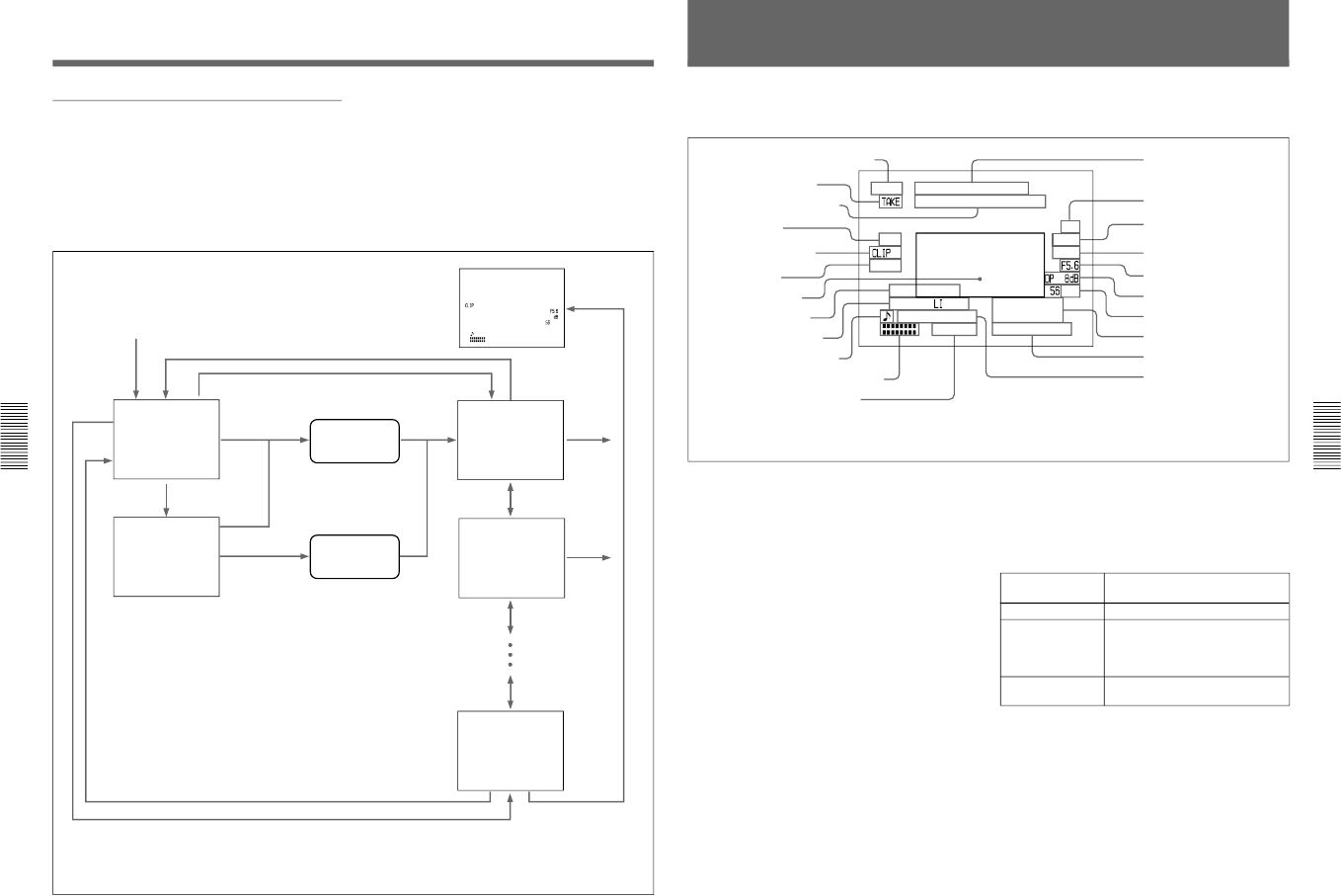
During normal operation, the following items can be
indicated in the viewfinder.
REC TAPE NEAR END
TCG 2:34 56:1:00
NG
AOBLC
A
TA TWU
EZ
E
VS
R
ND
08 4429
224MP
RO : SRDERP
S1/00:0S1
:
W
OL
EFOUZC
189
S
HGT
:
3-520
-K-O
K
M
1
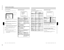
Viewfinder Normal Indications
The significance of each of the indications shown in
the figure is as follows.
1 VTR operation status indication
This indicates the VTR’s current operation status
(REC, PLAY, etc.).
2 TAKE/CUE indication
This displays a TAKE or CUE indicator when using
the ClipLink function and recording with the DSR-1/
1P.
TAKE: When recording in Mark mode, this
indication appears when a Mark IN point is set
and disappears when the next Mark OUT point is
set.
CUE: When recording in CUE mode, this indication
appears for about 1 second when a cue point is set.
3 Recording time or time data indication
This shows the following values.
•When the REC TIME switch on the camera is in the
TTL position: The total recording time
•When the REC TIME switch on the camera is in the
DUR position: The duration of the current recording
cut
•With a VTR connected, when the REC TIME switch
on the camera head is in the OFF position and the
item TC IND in advanced menu page 6 is set to
“ON”: A time data value from the VTR depending on
the DISPLAY switch settings on the VTR as shown
in the following table
When using the DSR-1/1P, time data values appear
during playback, fast forward, rewind, or recording
review.
4 NG indication
An “NG” (No Good) indicator appears if you
designate a recorded scene as “NG” when using the
ClipLink function and recording with the DSR-1/1P.
!£ VTR warning indication
a), b)
!¢ EZ mode indication
!∞ ATW indication
!§ EVS indication
!¶ Lens f-stop indication
c)
!• Gain indication
c)
!ª Filter setting indication
c)
@º Clock indication
a), b), c), d)
@¡ Voltage/error indication
@™ Shutter setting indication
c)
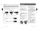
1 VTR operation status indication
a), b)
2 TAKE/CUE indication
a)
3 Recording time or time data
indication
a), b), c)
4 NG indication
a)
5 Clip mode indication
a)
6 Clip remaining
indication
a)
7 Status display area
8 EZ FOCUS indication
9 LOW LIGHT indication
c)
0 Camera microphone output
indication
c)
!¡ Audio recording level indicators
a), b), c)
!™ Tape remaining indication
a), b), c)
a) Displayed only when a DSR-1/1P is connected.
b) Displayed only when a PVV-3/3P is connected.
c) Whether or not to display can be selected by menu setting.
d) This is recorded over the picture being shot.
DISPLAY switch
setting
Time data displayed
COUNTER CNT: Tape transport time
TC TCG: a time code from the time code
generator
TCR: a time code from the time code
reader
U-BIT UBG: a user bit value from the user
bit generator