


1-29
DXC-D30WS/P(E)/V1
44
Chapter 3 Shooting
Chapter 3 Shooting
4
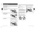
Release the REV or FWD button when you find
the tape location where you wish to continue
shooting.
The DSR-1/1P enters recording pause mode.
5
Press the VTR button on the camera head or the
lens.
The DSR-1/1P starts recording.
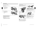
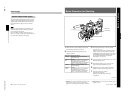
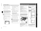
Using the Freeze Mix Function
The freeze mix function superimposes a freeze-frame
image of a previously recorded shot on the shooting
image displayed on the viewfinder screen.
You can use this function to easily frame a subject
within the same framework from a previous shot.
Note
When the camera head is in EZ mode, the freeze mix
function is disabled. Release the EZ mode beforehand.
(See page 12.)
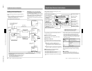
1
Dock the DSR-1/1P to the camera head and
connect a color monitor to the MONITOR OUT
connector.
2
Perform steps 2 to 10 from “Basic Procedure for
Shooting” (page 39).
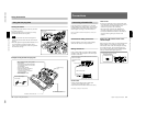
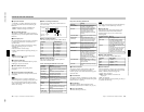
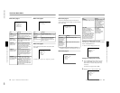
3
Access basic menu page 7 and move the cursor to
FREEZE.
For details of menu operations, see “Basic Menu
Operations” (page 51).
MARK/CUE:MARK
mFREEZE:OFF
CHG REEL NO:
(YESm4)
Shooting with the DSR-1/1P
4
Play back the tape on which the image to be used
for framework alignment has been recorded.
For details of the playback operation, see the operating
instructions for the DSR-1/1P.
A color playback image is displayed on the color
monitor’s screen.
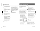
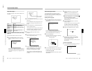
5
Press the UP/ON button when you see the image
you want to freeze.
The frozen playback image is displayed, mixed
with the shooting image, in monochrome. The
indication “FREEZE MIX ON” appears on the
screen.
To change the freeze-frame image
Press the DSR-1/1P’s PLAY button.
This returns to the screen shown in step 3 above,
and color playback mode begins.
Use the DSR-1/1P’s tape transport buttons to find
the desired image and then perform step 5 again.
6
Once you have framed your subject, press the UP/
ON button to cancel the freeze function.
This returns to the screen shown in step 3.
7
Find the recording start point or insert a new
cassette for recording, then begin recording.
Note
If you use the DSR-1/1P’s tape transport buttons
during back space editing, the back space editing mode
will be stopped. When you were using the ClipLink
function when shooting, If you simply restart the
recording you will lose any ClipLink data that was
recorded. To avoid this, press the DSR-1/1P’s
ClipLink CONTINUE button before restarting
recording.
For details, see the operating instructions for the DSR-1/1P.
Chapter 4 Viewfinder Screen Indications and Menus
45
Chapter 4 Viewfinder Screen Indications and Menus
MENU
STATUS
Chapter 4 Viewfinder Screen Indications and Menus
Viewfinder Screen Indications
There are four types of indication screen which appear
in the viewfinder, as follows.
•Normal indications
These show the operating state of the camera and
connected VTR. (See page 47.)
•Status indications
Pressing the MENU/STATUS switch up while the
normal indications are present calls a display of
current settings. (See page 50.)
•Basic menu
These provide settings for the lens iris, shutter speed
and so forth, and also a titling screen. (See the
section “Viewfinder Basic Menu” page 51.)
•Advanced menu
These provide settings for the center marker, zebra
pattern, viewfinder screen indications, and so forth.
(See the section “Viewfinder Advanced Menu” page
57.)
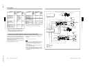
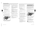
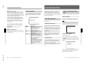
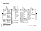
Changing the Viewfinder Display
Use the buttons and switches shown in the following
figure to switch the viewfinder display among the
normal indications, basic menu pages and advanced
menu pages.
Displaying the normal indications and
switching to the basic menu
To display the normal indications, move the POWER
switch to the ON position.
To switch to and from the basic menu, use the MENU/
STATUS switch.
DOWN/OFF button
POWER switch
UP/ON button
MENU/STATUS switch
Display by moving the
POWER switch to the
ON position.
Normal indications
Page 1
a)
Page 2
Page 9
b)
Switch by pressing the
MENU/STATUS switch up.
Switch by pressing
the MENU/STATUS
switch down.
Basic menu
Display by holding the
MENU/STATUS switch up
while the normal
indications are present.
a) The camera head’s self diagnostics results are automatically
displayed only when an abnormality has been detected.
b) The menu configuration differs according to the camera
head’s switch settings, the connected VTR, and the type of
input signal. A nine-page configuration results when all of the
basic menu pages are displayed.
REC
TCG 2:34 56:1:00
NG
AOBLCTAU
ND
08 4429
224MP
S1/00:0S1
:
W
OL
EFOUZC
189
S
HGT
:
-K-O
K
M
mCHECK DIAG
(YESm4)
mA.IRIS:±0
DTLLEV: ±0
M.BLACK:±0
STRETCH:±0
SHUTTER:OFF
mTITLE IND?
T : AUTO/A
RS:STD
E : STD
+ : OFF
E
I
I
I
L
C
H
.
I
C
W
A
F
D
OFF:SS
0
BATT: 13.0V
Status indications