


1-32
DXC-D30WS/P(E)/V1
50
Chapter 4 Viewfinder Screen Indications and Menus
Chapter 4 Viewfinder Screen Indications and Menus
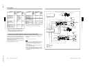
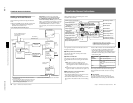
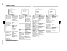
@¡ Voltage/error indication
The current voltage is displayed whenever the camera
head’s power supply voltage dips below 11.0 V DC.
However, you can also display the current voltage at
any time by pressing and holding the MENU/STATUS
switch in the upward position (the display is shown for
as long as you hold the switch upward).
An error message is displayed when an abnormality
has been detected by the auto diagnostic function
(page 51). If there is a voltage drop below 11.0 V DC
and an error has been detected, the low voltage
indication alternates at one-second intervals with the
error indication.
If an error message appears, contact your Sony dealer.
If using a VTR and an Anton Bauer Intelligent
Battery System
The remaining battery capacity is shown as a
percentage.
@™ Shutter setting indication
When the SHUTTER switch has been set to ON, the
shutter speed or CLS frequency set in basic menu page
2 is displayed here.
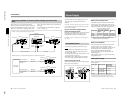
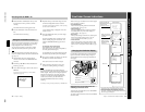
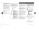
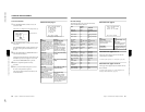
Viewfinder Normal Indications
Status Indications
If you set the MENU/STATUS switch to STATUS
while a menu is being displayed, the camera head’s
current setting status will be shown in this display
area.
T : AUTO/A
RS:STD
E : STD
+ : OFF
E
I
I
I
L
C
H
.
I
C
W
A
F
D
OFF
BATT:
:SS
13.0V
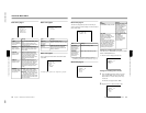
a) When both the DCC+ and DynaLatitude
functions are set to OFF
Display
Description
WHITE White balance adjustment method
selection (PRE/A/B) and color
temperature during auto white
balance adjustment
A.IRIS
FILE STD (when not using the setup files),
or a selected file name (when using
the setup files)
DCC+ or DL
Iris adjustment method selection
(STD/SPOT L/BACK L)
For DCC+ indication: ON with the
OUTPUT/DL/DCC+ switch set to
CAM/DCC+ (DCC+ ON), and OFF
with the switch set to CAM/DL and DL
in advanced menu page 2 (page 57)
set to OFF (both DCC+ and
DynaLatitude OFF).
For DL indication: When setting the
OUTPUT/DL/DCC+ switch to DL and
DL in advanced menu page 2 to OFF
(DynaLatitude OFF), LOW, STD or
HIGH is displayed according to DL
LVL setting in basic menu page 3
(page 52).
a)
Chapter 4 Viewfinder Screen Indications and Menus
51
Chapter 4 Viewfinder Screen Indications and Menus
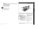
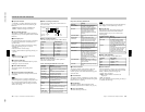
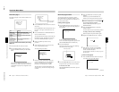
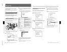
Viewfinder Basic Menu
To display the basic menu pages, press the MENU/
STATUS switch downward while the normal
indications are being shown in the viewfinder. The
basic menu configuration can include up to nine pages
(the configuration depends on the switch settings and
the type of connected VTR).
Basic Menu Operations
The common operations on all basic menu pages are
described below.
To change the page or item
The cursor is moved downward each time you press
the MENU/STATUS switch down. Once the cursor
has reached the last item on a page, press down the
MENU/STATUS switch to go to the next page. When
the last page is being displayed, pressing down the
MENU/STATUS switch returns the display to the
normal indications.
The cursor is moved upward each time you press up
the MENU/STATUS switch. Once the cursor has
reached the first item on a page, pressing up the
MENU/STATUS switch returns the display to the
normal indications.
To change settings
After using the MENU/STATUS switch to move the
cursor to the item on which you will change the
setting, press either the UP/ON button or the DOWN/
OFF button to select the desired value.
To reset any item to its shipped settings, press the UP/
ON button and the DOWN/OFF button at the same
time.
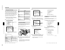
Contents and Settings of Each
Page
Each page’s contents and settings are described below.
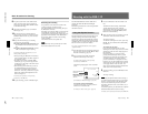
Basic menu page 1
This displays the self diagnostic results when the self
diagnostic function has detected an abnormality.
Note
The “CHECK DIAG” indication appears in the status
display area whenever the camera head’s automatic
self diagnostic function detects an abnormality. Be
sure to access this page and perform error checking.
mCHECK DIAG
(YESm4)
To perform error checking
Press the UP/ON button.
The error checking performs on the digital signal
processing (DSP) and memory circuits and the results
are displayed.
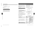
Example: If an abnormality is detected in the DSP
circuit.
DIAGNOSIS
DSP :ERROR
MEMORY:OK
This error message “DISP ERROR” appears when the
normal indications are displayed. If this message
appears, contact your Sony dealer.