


2-8
DXC-D30WS/P(E)/V1
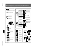
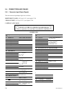
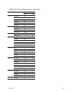
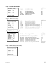
2-4-2. Connection Connector
Connections made with the connector panels during
installation or service, should be made with the connectors
or complete cable assemblies specified in the following
list, or equivalent parts.
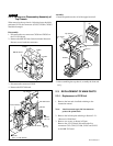
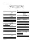
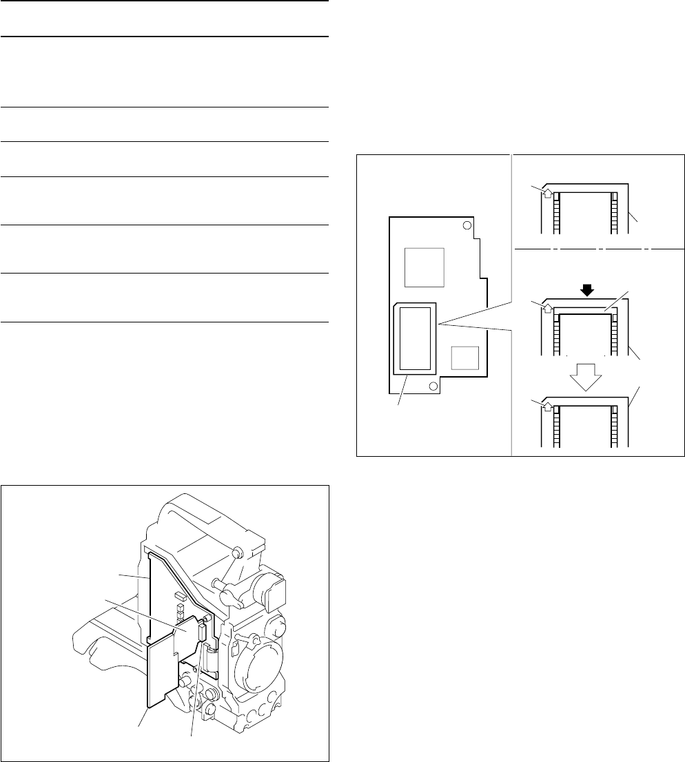
2-5. HOW TO HANDLE OF AT-125 BOARD
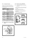
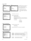
2-5-1. How to Attach of the Extension Board
EX-591
When using the extension board EX-591, attach as follows.
MB-785 board
AT-125 board
EX-591 board
CN2
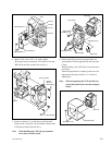
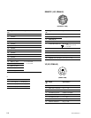
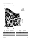
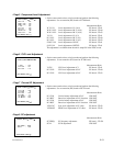
2-5-2. Replacement Way of ROM(IC102)
Note: When replacing the ROM, it is need that each
menu is reset.
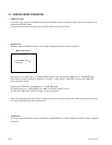
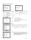
1. Slide the IC Socket cover in the A-arrow direction until
the click is heard. Remove the IC socket cover and the
former ROM.
2. Attach the new ROM on the IC socket.
3. Place the IC socket cover to have the clearance
between ROM and A-arrow side of IC socket cover.
(Refer to Fig.1.)
4. Slide the IC Socket cover in the opposite A-arrow
direction with holding the ROM.
ROM
IC
ROM
IC
ROM
IC
– With ROM mounted –
– How to attach (Fig.1) –
A
A
A
Push
Clearance
IC socket
cover
AT-110 board
IC108
IC102
IC socket
cover
Parts No. and name of connector
Connector Name
with cable
REMOTE 1-506-522-11
CONNECTOR, ROUND 10P, MALE
HIROSE HR 10A-10P-10P equality
(10P, FEMALE) or CCA-7-20 Cable assembly (optional)
VIDEO OUT 1-560-661-11
(BNC) PLUG, BNC
VF 9-994-797-01
(8P, FEMALE) CABLE, VF
LENS 1-564-360-11
CONNECTOR, 12P, MALE
(12P, FEMALE) HIROSE HR 10-10PA-12P equality
MIC 1-508-084-31
CONNECTOR, 3P, MALE
(3P, FEMALE) CANNON XLA-3-12C equality
VF 1-778-661-11
CONNECTOR, 20P, MALE
(20P, FEMALE) HIROSE HR 12-14PA-20PC equality