


3-7
DXC-D30WS/P(E)/V1
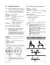
3-3-6. Chroma (VBS) Level Adjustment
Equipment: Verctorscope
To be extended: ES-22 board
Preparation:
• GAIN switch/Verctorscope → 75 % CAL
• Adjust the PHASE control on the vectorscope so that
the burst spot is overlapped to the 75 % axis.
• OUTPUT/DL/DCC+ switch/camera side → BARS
Test point: VIDEO OUT connector/camera side
Adjustment Procedure:
1. [for NTSC]
• SERVICE menu “PAGE 7”
→ B-Y BST :
Note: In case of NTSC, make sure that “R-Y BST”
must be “0”.
• Adjust the UP 4 switch or DOWN $ switch so that
burst spot is located at 75 % scale mark on the
vectorscope screen.
[for PAL]
• SERVICE menu “PAGE 7”
→ R-Y BST :
B-Y BST :
• Adjust “R-Y BST” and “B-Y BST” alternately by UP
4 switch or DOWN $ switch so that burst spot is
located at 75 % scale mark on the vectorscope
screen.
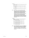
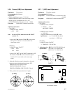
2. Adjust the following controls alternately so that each
beam spot stays inside the reference frame “4”.
1RV503 (B-Y LEV)/ES-22 board
1FL502 (PHASE)/ES-22 board
1RV504 (CHROMA VBS LEV)/ ES-22 board
3. Then, perform above procedure item 1 again.
[for NTSC] [for PAL]
R
M
G
C
Y
G
Y
L
B
R
M
G
C
Y
G
Y
L
B
100%
75%
3-3-7. Y (VBS) Level Adjustment
Equipment: Waveform monitor
To be extended: ES-22 board
Preparation: OUTPUT/DL/DCC+ switch/camera side
→ BARS
Test point: VIDEO OUT connector/camera side
Adjustment Procedure
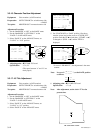
1. [for NTSC]
• SERVICE menu “PAGE 9”
→ SET UP : ON
MAT DEST : SMPTE
• SERVICE menu “PAGE 5”
→ S-UP LVL :
Adjust the UP 4 switch or DOWN $ switch.
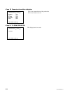
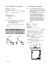
Specification : A = 7.5 ±0.5 IRE (See below
waveform) ---- NTSC only
[for PAL]
• SERVICE menu “PAGE 9”
→ COMP LVL : 525 (not 700)
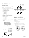
2. Adjusting point: 1RV501 (Y LEVEL)/ES-22 board
Specification: [for NTSC] B = 100 ±2 IRE
[for PAL] B = 700 ±10 mV
[for NTSC] [for PAL]
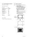
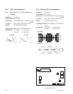
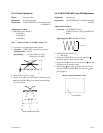
DL504
DL503
CN501
RV505
C (Y-C)
RV501
Y (VBS)
RV502
Y (Y-C)
FL502
RV504
C (VBS)
RV503
B-Y LEV
FL501
E1
TP1
DL501
FL503
DL502
ES-22 BOARD -A SIDE-