


3-9
DXC-D30WS/P(E)/V1
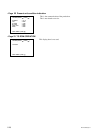
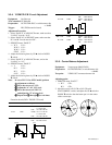
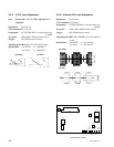
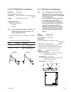
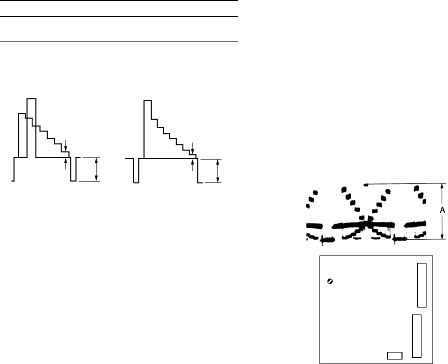
3-3-11. CCD Output Level Adjustment
Note : • Use a reflection type with chart for this
adjustment, therefore, control the light so
that the white area of chart is exactly 3200K
of color temperature.
• If use the pattern box, make sure that the
color temperature must be 3200K.
• Usually, this adjustment is not required.
Only when the output level of CCD unit is
large different from the specification.
• When the new CCD unit of spare parts is
replaced, this adjustment is not required
because of the correct adjustment at the
factory.
Object: Grayscale chart
Equipment: Oscilloscope
To be extended: VA-185 board
Preparation:
• OUTPUT/DL/DCC+ switch/camera side
→ CAM/DCC+
• WHITE BAL switch/camera side → PRESET
• Chart frame = Underscanned monitor frame
• Adjust the lens iris so that the video level at TP27/
extension board (VA-185 board) is 165 ±5 mV.
Trigger: HD (TP72/extension board)
Adjustment Procedure
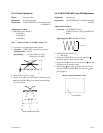
1. Test point: TP15/extension board (VA-185 board)
1RV1/PA-219 (B) board
Specification : A = 165 ±5 mV
2. Test point: TP21/extension board (VA-185 board)
1RV1/PA-221 (R) board
Specification : A = 165 ±5 mV
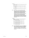
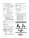
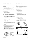
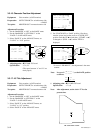
3-3-10. VF SYNC/BLKG Level Adjustment
Equipment: Oscilloscope
To be extended: ES-22 board
Preparation: OUTPUT/DL/DCC+ switch/camera side
→ BARS
Trigger: HD (TP84/extension board)
Adjustment Procedure
1. SERVICE menu “PAGE 7”
VF SYNC
→ VF BLKG
Note: For the adjustment procedure, at the first “VF
BLKG” adjustment is done, and next, “VF
SYNC” adjustment is done.
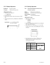
2. Adjust the following items by UP 4 switch or DOWN
$ switch.
Extension board (GND : TP81/ES-22 board)
Item Test Point Specification
VF BLKG TP82 NTSC : A = 50 ±10 mV
PAL : A = 50 ±10 mV
VF SYNC TP82 NTSC : B = 286 ±10 mV
PAL : B = 300 ±10 mV
[for NTSC] [for PAL]
B
A
B
A
RV1
CN2
CN3
PA-219 (B) BOARD
PA-221 (R) BOARD
- A SIDE -
- A SIDE -
CN1