


1-31
DXC-D30WS/P(E)/V1
48
Chapter 4 Viewfinder Screen Indications and Menus
Chapter 4 Viewfinder Screen Indications and Menus
5 Clip mode indication
A “CLIP M” or “CLIP C” indication appears when
you use the ClipLink function and record using the
DSR-1/1P.
CLIP M: Indicates shooting in MARK mode
CLIP C: Indicates shooting in CUE mode
6 Clip remaining indication
The number of available index pictures remaining is
displayed when you use the ClipLink function with the
DSR-1/1P.
7 Status display area
One of the following values or messages is displayed
to indicate the camera head’s current status or its
operation status.
•New values when changing camera head’s settings
•Messages indicating progress or results of
adjustments
•The camera head’s current settings
•SetupLog data recorded to tape during shooting (see
page 69)
Note
The status indication is not shown while the EZ
FOCUS indication 8 appears.
8 EZ FOCUS indication
This appears when the EZ FOCUS button is pressed,
enabling the “easy focus” function.
9 LOW LIGHT indication
This warning appears if the lighting level is
inadequate.
0 Camera microphone output indication
This appears when there is an input from the camera
microphone.
Note
This indication serves as a check on whether the
camera microphone is operating correctly, but it does
not provide confirmation that the VTR is recording
sound. Check that the audio recording levels on the
VTR are set correctly.
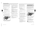
!¡ Audio recording level indicators
These show the recording levels of audio channels 1
and 2 on the VTR.
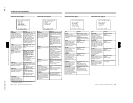
!™ Tape remaining indication
This shows the tape remaining in the VTR as follows.
!£ VTR warning indication
This shows warning indications about operation or
status of the connected VTR.
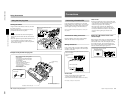
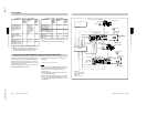
When connecting the DSR-1/1P or PVV-3/3P
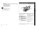
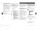
Viewfinder Normal Indications
Channel 1
Channel 2
–20 dB
–
∞
+3 dB
0 dB
0 dB
–2 dB
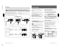
PVV-3/3P
DSR-1/1P
Indication Tape remaining
F-30 At least 30 minutes
30-25 25 - 30 minutes
25-20 20 - 25 minutes
20-15 15 - 20 minutes
15-10 10 - 15 minutes
10-5 5 - 10 minutes
5-0 2 - 5 minutes
5-0 (flashing) 0 - 2 minutes
Indication Meaning
NO TAPE There is no tape loaded.
REC INHIBIT
The tape is in the recording inhibited
state.
LOW BATT.
The battery is almost exhausted.
BATT. END
The battery is exhausted.
TAPE NEAR END The tape is near the end.
TAPE END The tape is at the end.
CHECK REMOTE
(PVV-3/3P only)
A device other than a remote control
unit (e.g. headphones) is connected to
the REMOTE connector.
SERVO The servo lock has been lost.
HUMID There is condensation.
RF The video heads are clogged, or there
is some other fault in the recording
system.
SLACK
The tape is not wound properly.
OXIDE TAPE
(PVV-3/3P only)
An oxide tape has been loaded. (The
tape is automatically ejected.)
Chapter 4 Viewfinder Screen Indications and Menus
49
Chapter 4 Viewfinder Screen Indications and Menus
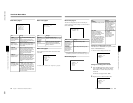
Only when connecting the DSR-1/1P
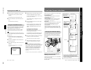
!¢ EZ mode indication
This appears when the camera head is in EZ mode.
In the EZ mode, the auto tracing white balance
function operates, so the ATW indication also appears
at the same time.
!∞ ATW indication
This appears when the ATW button is pressed, turning
the indicator on. It indicates that the auto tracing white
balance function is operating.
!§ EVS indication
This appears when the EVS (Enhanced Vertical
definition System) function is enabled. (See page 75.)
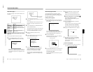
!¶ Lens f-stop indication
This shows the f-stop of the lens.
Note
Depending on the lens being used, this indication may
differ slightly from the actual f-stop on the lens.
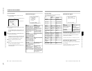
!• Gain indication
This shows the gain value, and the settings of the
HYPER GAIN switch and the DPR (Dual Pixel
Readout) function (see page 57) as shown in the
following table.
!ª Filter setting indication
This shows the setting of the FILTER control.
@º Clock indication
The clock indication is shown in one of the following
ways (according to the CLOCK IND setting of CAM,
BARS, or OFF in advanced menu page 8).
CAM: Always displayed.
BARS: Displayed whenever color bars are
displayed.
OFF: Not displayed.
If the clock indication is displayed during recording, it
is recorded onto the image.
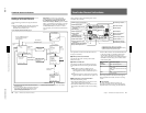
Indication
Meaning
50P CONNECT Connection with the PRO 50-pin
connector on the DSR-1/1P.
(Freeze mix function is disabled.)
MP TAPE An incorrect type of cassette has
been loaded. (The cassette is
automatically ejected and the
indication disappears in about two
seconds.)
CLIP DATA ERR Abnormality of the cassette memory
data.
AUDIO 48kHz
(4 flashes/s)
At back space editing, audio
recording mode has changed from
32 kHz mode (4-channel mode) to
48 kHz mode (2-channel mode).
AUDIO 32kHz
(4 flashes/s)
At back space editing, audio
recording mode has changed from
48 kHz mode (2-channel mode) to
32 kHz mode (4-channel mode).
ERROR:91-13F
Example indication Meaning
18dB Gain setting is 18 dB.
DPR 18dB The DPR function is enabled.
In this case the DPR function
approximately doubles the gain (an
increase of 6 dB) over the current
gain setting (in this case 18 dB).
HYPER The HYPER GAIN switch is in the
ON position.
In this case the hyper gain function
increases the gain by a factor of
about 60 with respect to 0 dB
regardless of the current gain
setting (that is, increased to 36 dB).
Failure in loading or saving the
cassette memory data.
CLIP CONT?
Asking whether you will continue
shooting in ClipLink mode or not
when the cassette contains ClipLink
data. (The indication disappears
when you press the ClipLink
CONTINUE button on the DSR-1/
1P or start the next shooting without
pressing it.)
CLIP NEAR END
CLIP END Impossible to record any more clip
shots.
At back space editing in ClipLink
mode, capacity for only 1 to 3 index
pictures remains.
Indication Filter setting
3200 1 (3200K)
56ND 2 (5600K +
1
/
8
ND)
5600 3 (5600K)
56ND 4 (5600K +
1
/
64
ND)