


1-24
DXC-D30WS/P(E)/V1
Chapter 2 Fitting and Connections
34
Chapter 2 Fitting and Connections
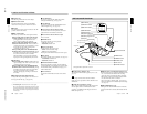
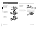
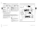
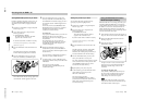
VTR selector settings on the CA-537/537P
a) Set the audio input level on the VO-6800/6800PS to –60
dB.
b) When the BVV-5/5PS is used as a portable VTR, a VA-5/
5P VTR Composite/Component Adaptor is required.
c) Set the input selector switch on the AG-7400 to Y/C.
VTR selector settings on the CA-327/327P
a) Set the audio input level on the VO-6800/6800PS to –60
dB.
b) Set the input selector switch on the AG-7400 to Y/C.
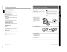
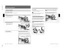
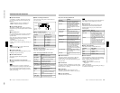
Connected VTR
VTR
selector
switch
setting
Video output
signal
Audio
output
signal
level
Sony broadcast and
professional VTRs:
BVU-150/150P and
VO-6800/6800PS
a)
1 Composite –60 dB
Sony professional
VTRs: VO-8800/8800P
and EVV-9000/9000P
3 Y/C –60 dB
Panasonic AG-6400
VHS VTR
Connected VTR VTR
selector
switch
setting
Video output
signal
Audio
output
signal
level
Sony broadcast and
professional VTRs:
BVU-150/150P, VO-
6800/6800PS
a)
, BVW-
50/50P and BVV-5/
5PS
b)
1 Composite
(BVU-150/
150P and VO-
6800/6800PS)
or component
(BVW-50/50P
and BVV-5/
5PS)
–60 dB
Sony professional
VTRs: VO-8800/
8800P and EVV-9000/
9000P
3 Y/C –60 dB
2 Composite –20 dB
Panasonic AG-7400 S-
VHS VTR
c)
and JVC
BR-S405 S-VHS VTR
3 Y/C
–20 dB
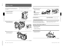
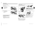
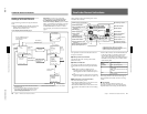
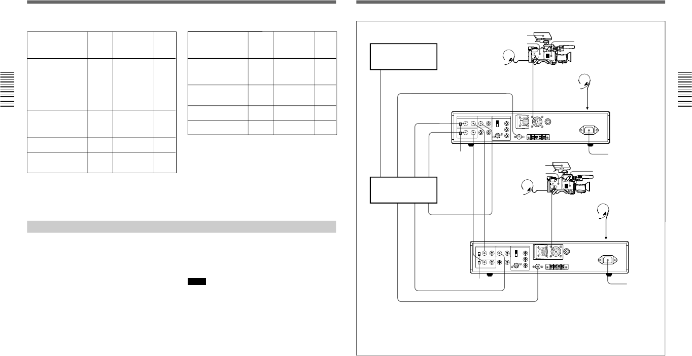
Connecting a Number of Cameras (Using a Camera Control Unit)
When using a number of cameras in the studio, it may
be necessary to use a CCU-M5/M5P/M7/M7P Camera
Control Unit to provide video and color sync between
cameras, and special effects and other devices to allow
switching, wipes and so forth.
In the studio it may also be convenient to use a DXF-
40B/40BCE/50B/50BCE Viewfinder.
The figure in the next page shows an example studio
configuration.
For details, consult your Sony dealer.
Notes
•When using the CCU-M5/M5P, put the camera head
into the EZ mode off state beforehand (see page 12).
(Otherwise, it may be impossible to access the
advanced menu.)
•With the DXC-D30/D30P, color matrix switching on
the CCU-M5/M5P is invalid.
•When the DL in advanced menu page 2 is set to ON
(see page 57) and the OUTPUT/DL/DCC+ switch is
set to DL, knee adjustment does not function on the
CCU-M7/M7P.
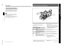
Connections
Panasonic AG-6400
VHS VTR
2 Composite –20 dB
Panasonic AG-7400 S-
VHS VTR
b)
4 Y/C –20 dB
Chapter 2 Fitting and Connections
Chapter 2 Fitting and Connections
35
INTERCOM
VIDEO IN
PGM OUT
TALLY/INTERCOM
PGM OUT
VBS OUT
RETURN VIDEO IN
GEN LOCK IN
TALLY/INTERCOM
VIDEO IN
VIDEO IN
GEN LOCK OUT
RETURN VIDEO OUT
VBS OUT
CAMERA
CAMERA
TALLY/INTERCOMVBS OUT
GEN LOCK IN
RETURN VIDEO IN
1
4
2
2
3
3
3
3
3
3
43
1
TALLY/INTERCOM
DXC-D30/D30P
CA-537/537P
Headset
Headset
VTR
Switcher, special
efects unit, etc.
75Ω termination switch to ON
CA-537/537P
DXF-40B/40BCE
or DXF-50B/50BCE
Headset
Headset
INTERCOM
(on the front)
INTERCOM
(on the front)
CCU-M5/M5P
Camera Control
Unit
CCU-M5/M5P
Camera Control
Unit
To AC power supply
DXC-D30/D30P
To AC power supply
Cables used
1 Power cord (supplied)
2 CCZ-A Camera Cable
3 BNC cable
4 DIN 4-way cable
DXF-40B/40BCE or DXF-50B/50BCE
75Ω
termination
switch to OFF