


1-15
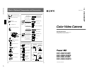
DXC-D30WS/P(E)/V1
Chapter 1 Overview
16
Chapter 1 Overview
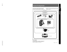
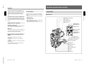
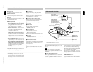
Location and Function of Parts
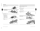
7 REMOTE connector 1 (mini-jack)
Use this connector to connect the switch for enabling
remote operation of the ClipLink function.
For details of connectable switches, contact your Sony
dealer.
8 MONITOR OUT connector (BNC)
Outputs both the camera video and the character
information as displayed on the viewfinder screen.
You can connect an optional LCD color monitor to this
connector.
9 VIDEO OUT connector (BNC)
This outputs the video signal captured by the camera.
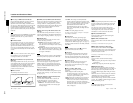
0 REMOTE connector 2 (10-pin)
Connect the optional RM-M7G Remote Control Unit
to this connector. Set the CAMERA HEAD SELECT
switch on the bottom of RM-M7G to 1.
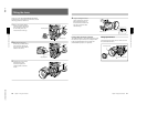
Notes
When using the RM-M7G, note the following points.
•When operating the camera head from the camera
control unit, connect the RM-M7G to the camera
control unit.
•EZ mode cannot be used if the RM-M7G is
connected to the camera head.
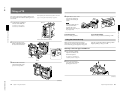
!¡ LENS connector (12-pin, for
2
/
3
-inch lens)
Connect the lens connector.
!™ VF (viewfinder)connector (8-pin)
This is the connector for the DXF-40B/50B (or DXF-
40BCE/50BCE) viewfinder.
Note
When using this connector, do not connect a DXF-701/
701CE viewfinder to the VF connector on the front of
the camera head.
!£ VTR connectors (PRO 76-pin DIGITAL and
PRO 50-pin)
Connect a dockable VTR. A PRO 76-pin DIGITAL
connector is for the DSR-1/1P and a PRO 50-pin
connector is for the PVV-3/3P or a camera adaptor.
Chapter 1 Overview
Chapter 1 Overview
17
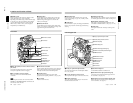
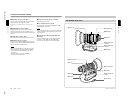
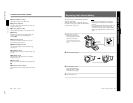
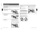
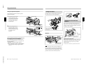
VCL-916BYA Zoom Lens
RET
W
T
M
A
1 Focusing ring
2 Manual zoom control
3 Iris ring
4 RET button
5 VTR button
6 Ff adjustment ring
7 MACRO button
8 MACRO ring
9 Zoom remote control
connector
0 Focus remote control
connector
!¡ ZOOM selector
!™ Power zoom switch
!£ Iris selector
!¢ Instant automatic iris
button
!∞ Lens connector