


1-16
DXC-D30WS/P(E)/V1
Chapter 1 Overview
18
Chapter 1 Overview
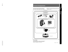
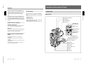
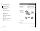
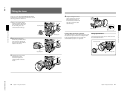
1 Focusing ring
Turn this ring to focus the lens on the subject.
2 Manual zoom control
For direct manual zoom control, set the ZOOM
selector to the “M” position, and turn this control.
3 Iris ring
For manual iris control, set the iris selector to the “M”
position, and turn this control.
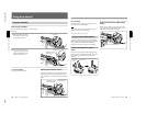
4 RET (return) button
This allows you to check the video signal as follows.
When operating with a portable VTR connected
via other equipment: when the VTR is recording,
pressing this button connects the E-E video
signal
1)
from the VTR to the viewfinder.
When operating with a DSR-1/1P or PVV-3/3P
mounted on the camera head: when the VTR is in
recording pause mode, press this button to review
the last few seconds of the recording in the
viewfinder (recording review).
When operating with a CCU-M3/M3P/M5/M5P
M7/M7P Camera Control Unit connected: pressing
this button connects the return video signal from
the camera control unit to the viewfinder.
When this button is not pressed, the viewfinder
displays the video signal captured by the camera.
5 VTR button
When operating with a VTR: this button starts and
stops recording on the VTR. Press it once to start
recording, and once more to stop.
When operating with a CCU-M3/M3P/M5/M5P
M7/M7P Camera Control Unit connected: pressing
this button connects the return video signal from
the camera control unit to the viewfinder.
(Starting and stopping recording is controlled on
the VTR.)
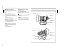
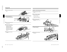
6 Ff (flange focal length) adjustment ring
To adjust the flange focal length, loosen the screw on
this ring, then turn the ring. (See page 80.)
7 MACRO button
For close-up work, hold this button down while
turning the MACRO ring. (See page 82.)
8 MACRO ring
For close-up work, hold the MACRO button down
while turning this ring. (See page 82.)
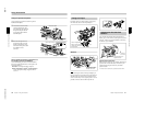
9 Zoom remote control connector (8-pin)
For remote control of zoom operations, connect an
optional LO-23 Lens Remote Control Unit.
!º Focus remote control connector (3-pin)
This is not used.
!¡ ZOOM selector
This selects the mode of zoom operation.
S (servo): power zoom
M (manual): manual zoom
!™ Power zoom switch
Use this to carry out a power zoom.
W end: zoom toward wide angle
T end: zoom toward telephoto
Pressing the switch harder increases the zoom speed.
!£ Iris selector
This selects the mode of iris operation. (See page 81.)
A (automatic): automatic iris
M (manual): manual iris
!¢ Instant automatic iris button
While using manual iris control, press this button to
switch temporarily to the automatic iris control setting.
The automatic setting is maintained as long as you
hold the button down.
!∞ Lens connector
Connect this to the LENS connector on the camera
head.
1) E-E video signal: “electric-to-electric” video signal.
This is an output from the VTR of the input video signal
which has passed through internal electrical circuits, but
has not been converted to a magnetic signal in the heads
or on the tape.
..........................................................................................................................................................................................................
Location and Function of Parts
Chapter 1 Overview
Chapter 1 Overview
19
SHUTTER GAIN UP
TAKE
BATT
REC
TALLY
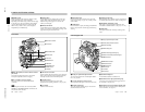
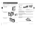
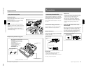
DXF-701/701CE Viewfinder
1 BATT indicator
2 TAKE/TALLY indicator
3 REC/TALLY indicators
4 SHUTTER indicator
5 GAIN UP indicator
6 Eyepiece focusing knob
7 Accessory fixing screw hole
8 Tally lamp
9 Eyepiece release catch
0 BRIGHT control
!¡ CONTRAST control
!™ PEAKING control
!£ TALLY switch
!¢ Viewfinder connector
Microphone holding screw
Microphone holder
Microphone
a)
Eye cup
a) Not supplied with the optional DXF-701/701CE
3 REC/TALLY (recording/tally) indicators (red)
•From the time when you press the VTR button on the
lens or camera head, this flashes until recording
starts, then stays on continuously during recording.
•When using a camera control unit, this lights when
the video from this camera is selected.
•This is also used to indicate a fault. (See page 86.)
•The lower indicator can be disabled by menu setting.
(See page 58.)
4 SHUTTER indicator (red)
This lights when the SHUTTER switch is in the ON
position. (If the EVS is selected, the indicator will not
light.)
1 BATT (battery) indicator (red)
This indicates when the battery capacity is low. (See
page 37.)
Note
When using a camera control unit, this indicator
flashes when you operate the controls, but this is not a
malfunction.
2 TAKE/TALLY indicator (orange)
When using the ClipLink function while shooting, this
indicator lights when the TAKE button has been
pressed to set a Mark IN point and goes out when a
Mark OUT point is set.