


2-18
DXC-D30WS/P(E)/V1
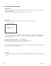
• Page 21 Selfdiagnosis 4
RC-PMPD
The details of check result for synchronization signal input and the
internal RAM in RC LSI are displayed.
800H: The internal RAM of RC LSI is abnormal.
004H: The input HD signal (IC520, pin64) to the RC LSI is
abnormal.
002H: The input VD signal (IC520, pin65) to the RC LSI is
abnormal.
001H: The input CF signal (IC520, pin63) to the RC LSI is abnormal.
RC-CY
The details of check result for the connection regarding the Y signal
between PR LSI and RC LSI are displayed.
400H: The connection between PR IC411 pin94 and IF IC520 pin97
is abnormal.(The No.10 of Y signal)
200H: The connection between PR IC411 pin93 and IF IC520 pin98
is abnormal.(The No.9 of Y signal)
100H: The connection between PR IC411 pin92 and IF IC520 pin99
is abnormal.(The No.8 of Y signal)
080H: The connection between PR IC411 pin91 and IF IC520 pin100
is abnormal.(The No.7 of Y signal)
040H: The connection between PR IC411 pin90 and IF IC520 pin101
is abnormal.(The No.6 of Y signal)
020H: The connection between PR IC411 pin89 and IF IC520 pin103
is abnormal.(The No.5 of Y signal)
010H: The connection between PR IC411 pin88 and IF IC520 pin104
is abnormal.(The No.4 of Y signal)
008H: The connection between PR IC411 pin86 and IF IC520 pin105
is abnormal.(The No.3 of Y signal)
004H: The connection between PR IC411 pin85 and IF IC520 pin106
is abnormal.(The No.2 of Y signal)
002H: The connection between PR IC411 pin84 and IF IC520 pin107
is abnormal.(The No.1 of Y signal)
001H: The connection between PR IC411 pin83 and IF IC520 pin108
is abnormal.(The No.0 of Y signal)
RC-CCR
This display item is not used.
RC-CCB
This display item is not used.
Note : If the input of synchronization signal to the PR LSI or RC
LSI is abnormal, the connection check between PR LSI and
RC LSI is detected the abnormality.
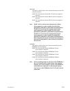
PAGE21(NEXT PREV )
EXIT MENU (YES )
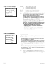
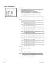
ERROR DISP 3/3
DSP COM. 000H:
MEMORY 000H:
RC- CCR 000H:
RC- CCB 000H:
RC- CY 000H:
RC- PMPD 000H
1
:
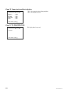
DISP SELECT
: