4-2 Connectors, Switches, Jumpers, and LEDs
System I/O Board Connectors
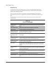
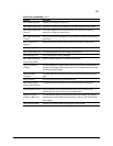
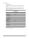
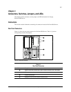
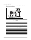
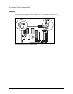
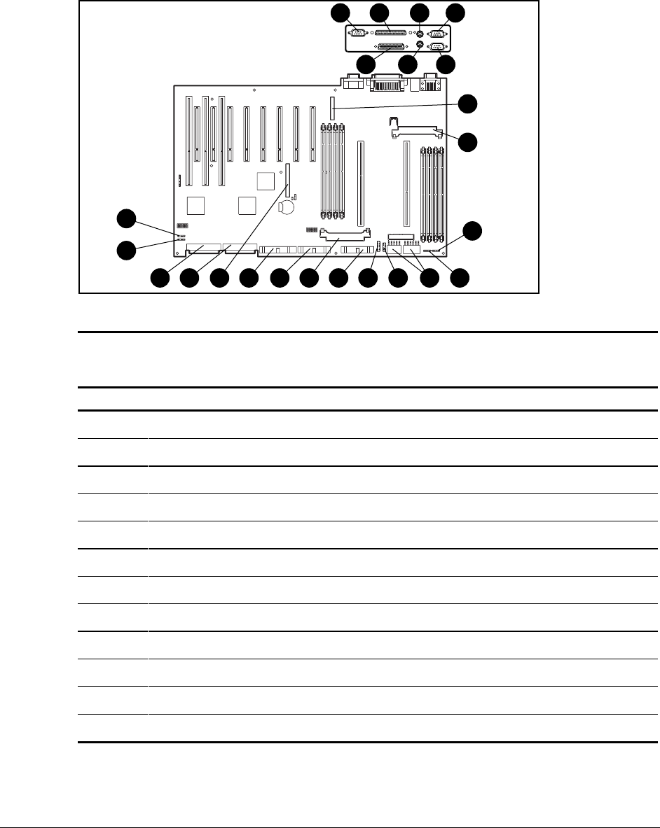
Figure 4-2 shows the system I/O board connectors for ProLiant 3000 Servers. Table 4-2 gives
the corresponding connector descriptions.
1
7
9
121314151617
6 5
2 3 4
18192021
22
23
11
8
10
Figure 4-2. System I/O board connectors
Table 4-2
System I/O Board Connectors
Reference Connector Reference Connector
1 Video = Power Switch
2 External SCSI > Power Supply
3 Mouse ? Integrated Management Display (IMD)
4 Serial Port B @ Processor Power Module 2
5 Serial Port A A Diskette Drive
6 Keyboard B CD-ROM Drive
7 Parallel/Printer Port C I
2
O
8 Auxiliary Fan D SCSI Port 2
9 Processor Power Module 1 E SCSI Port 1
: CPU Redundant Fan F I/O Fan
; CPU Fan G I/O Redundant Fan
< Power


