


11
Features
Chapter 1 Overview
UHF synthesized tuner (supplied separately) without
using any connecting cable.
• The audio signals to be recorded on the disc can be freely
selected from the audio inputs to the stereo microphone,
AUDIO IN connectors and the UHF synthesized tuner,
and assigned to any desired audio channel.
Input/Output Features
Equipped with an i.LINK connector
The i.LINK connector on this unit supports the following
two functions.
DV stream output (AV/C
1)
mode connection): A DV
stream can be output from the i.LINK connector on
this unit, and recorded on a DV recorder or nonlinear
editor supporting DV. For recording and playback in
MPEG HD format, a down-converted DV stream can
be output.
File access from a computer (FAM
2)
connection): An
FAM connection between this unit and a computer
allows the video, audio, and metadata information on
the disc to be read and written as files. (The data can
be written and read as normal files on a computer.)
With this function, a nonlinear editing device
connected to this unit can be used for direct HD video
editing or simple Proxy AV data editing, enabling a
more efficient workflow.
1) Audio/Video Control
2) File Access Mode
Other signal input/output connectors
SDI output connector
This connector outputs video signals with embedded
audio.
You can switch between HDSDI and SDSDI signal output
by a menu setting. The video and audio output from this
connector can be recorded on an external HD device.
Select HDSDI signal output when you are recording with
an external HD device connected. Select SDSDI signal
output when you are recording with an external SD device
connected.
Composite video output connector
50i/25P video is output as a PAL signal, 60i/30P video is
output as an NTSC signal, and 23.98P video is output as an
NTSC signal which has undergone 2-3 pulldown
processing.
A Y signal is output when the 23.9P OUTPUT menu item
is set to PSF.
Timecode input/output connectors
The unit is provided with one input connector and one
output connector.
GENLOCK connector
The SD or HD reference signal can be input to apply a
genlock to the camera.
Video light connector
There is an interface connector for a maximum 50 W video
light, and a control switch. Depending on the switch
setting, the light can be turned on and off as recording
starts and stops.
Remote control connector
Connect the RM-B150/B750 remote control unit (supplied
separately) or other remote commander, to allow remote
operation of the shooting functions of this unit.
Audio output connectors
The unit is provided with XLR connectors (5-pin, balanced
output), allowing stereo output.
Earphone jack (monaural/stereo)
Audio channels to be monitored can be selected with the
MONITOR switch on the side of the unit. Switch between
monaural and stereo using the menus.
Other Features
User-friendly interface functions
ASSIGN (assignable) switches
The unit is provided with four ASSIGN switches; two on
the front and the others on the top of the grip. You can
assign various functions to these switches. By assigning
frequently used functions to the switches, you can call up
the desired functions instantly, for example during
shooting operations. The functions that can be assigned are
as follows.
• Lens zoom control (telephoto/wide-angle)
• Easy focus function
• Turbo gain function
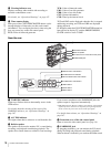
3.5-inch color LCD monitor
The LCD monitor on the side of the unit can be switched
to show the following images and data.
• Status information, including audio level meters for four
channels and timecode
• List of thumbnails of the video recorded on the
Professional Disc
• A playback image of the video recorded on the
Professional Disc
•The camera image