


138
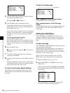
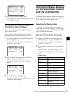
Setting the Status Display on the Viewfinder Screen and the LCD Monitor
Chapter 5 Menu Displays and Detailed Settings
2) When an Anton Bauer battery system or a BP-GL65/GL95 battery
pack is installed, the remaining battery power is shown as a
percentage value (%) according to the setting of this item.
INT: When one of the above batteries is installed, the remaining
power is shown as a percentage value (%) when there is a change
in the value or when the power is low.
AUTO: The remaining power is shown as a percentage value (%)
when one of the above batteries is installed. Otherwise the voltage
(VOLT) is displayed continuously.
VOLT: The voltage (VOLT) is displayed continuously.
VF DISP 2 page
3
Turn the MENU knob to select the desired setting
(ON, OFF, or value), and press the MENU knob.
4
Repeat steps 2 and 3 until you have set all of the
desired items.
Change Confirmation/Adjustment
Progress Messages
The messages indicating setting changes, progress and
consequence of adjustments, and the situations indicated
by these messages are as follows.
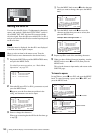
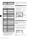
Setting change confirmation/adjustment progress
messages
1) The corresponding message is also displayed for about 3 seconds when the
SHUTTER switch is set to ON.
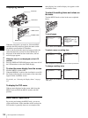
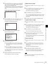
Setting the Marker Display
You can switch the display of the center and safety zone
markers on or off and select whether the area indicated by
the safety zone marker is 80%, 90%, 92.5%, or 95% of the
screen area.
(How to select an item in the menu screen: Turn the
MENU knob to move the b mark to the desired item.)
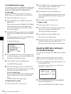
1
Display the MARKER page of the USER (or
OPERATION) menu, and press the MENU knob.
For details on menu operations, see “Basic Menu
Operations” on page 132.
2
Select the desired setting item, and press the MENU
knob.
You can set the following items on the MARKER
page.
3
Turn the MENU knob to select the desired setting, and
press the MENU knob.
4
Repeat steps 2 and 3 until you have set all of the
desired items.
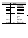
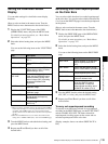
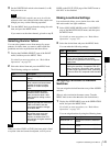
Item Description
DISP 5600K Displays “5600K”.
DISP FILTER Displays types of the ND filter.
DISP WHITE Displays selected white balance
memory.
DISP GAIN Displays gain value.
DISP SHUTTER Displays shutter speed and ECS
mode.
DISP AUDIO Displays audio level.
DISP DISC Displays remaining disc capacity.
DISP IRIS Lens iris setting indication
DISP LOW LIGHT “LOW LIGHT” indication when the
average video level is below a
certain threshold.
DISP INTERVAL “INTERVAL TIME” indication
during interval recording.
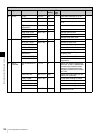
Situation Message to appear
The filter selection has been
changed
FILTER: n
(where n = 1, 2, 3, 4)
The gain setting has been
changed
GAIN: n
(where n = –3dB, 0dB, 3dB,
6dB, 9dB,12dB, 18dB, 24dB,
30dB, 36dB, 42dB, 48dB)
The setting of the WHITE
BAL switch has been
changed
WHITE: n
(where n = A CH, B CH,
PRESET) or ATW: RUN
The OUTPUT/DCC switches
has been set to DCC ON or
OFF
DCC: ON (or OFF)
The shutter speed and mode
setting has been changed
1)
SHUTTER: 1/100 (or 1/125,
1/250, 1/500, 1/1000, 1/2000,
ECS, SLS)
The black or white balance
has been adjusted
E.g. WHITE: OK
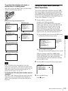
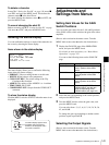
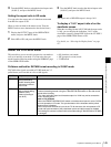
Item Description
MARKER If you want no markers to be
displayed, set to OFF.
CENTER To display the center marker, set
to ON.
SAFETY ZONE To display the safety zone, set to
ON.
SAFETY AREA Selects the safety zone area.
ASPECT To display the aspect marker, set
to ON.
ASPECT SELECT Selects the type of the aspect
marker. (14:9/13:9/4:3)
Situation Message to appear