


45
Connecting
Chapter 2 Preparations
Connecting
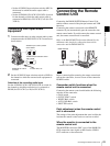
Production of some of the peripherals and related devices
described in this chapter has been discontinued. For advice
about choosing devices, please contact your Sony dealer or
a Sony sales representative.
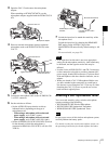
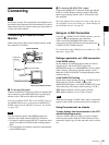
Connecting an External Video
Monitor
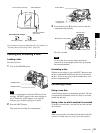
When using a Sony liquid crystal display monitor, make
the connections as follows.
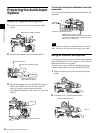
a To check an SDI signal
Connect the SDI OUT connector of this unit and the SDI
input connector of the LMD-9050 liquid crystal display
monitor with a 75Ω coaxial cable (not supplied).
You can use SDI OUTPUT SEL on the OUTPUT page of
the OPERATION menu to switch between HDSDI and
SDSDI output from the SDI OUT connector. For details,
see page 112.
Note the following points when HDSDI signals are
selected as the output from the SDI OUT connector.
• No signal is output from the SDI OUT connector when
signals recorded in DVCAM format are being played
back.
• Text information and markers cannot be superimposed
on the HDSDI output.
b To check an SD (NTSC/PAL) signal
Connect the VIDEO OUT connector of this unit and the
LINE A or LINE B input connector of the LMD-9050
liquid crystal display monitor with a 75Ω coaxial cable
(not supplied).
The items displayed on a monitor are same as the ones on
the viewfinder screen. For details, see “Status Display on
the Viewfinder Screen” on page 26.
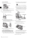
Using an i.LINK Connection
Using the (i.LINK) DV OUT S400 connector, you can
connect external equipment to the camcorder.
Video recorded in the MPEG HD format is down-
converted to the DVCAM format and output from the
(i.LINK) DV OUT S400 connector.
For connections using FAM (file access mode), see “File
Operation” (page 156).
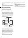
Settings required for an i.LINK connection
i.LINK MODE setting
Set the method of connection between this unit and an
external device. On the OUTPUT page of the
OPERATION menu, set i.LINK MODE to AV/C (Audio/
Video Control). (The factory default setting is AV/C.)
Make the i.LINK AUDIO OUT setting depending on the
connected device.
i.LINK AUDIO OUT setting
Set the audio output channels for the (i.LINK) DV OUT
S400 connector. On the AUDIO-2 page of the
MAINTENANCE menu, set i.LINK AUDIO OUT to one
of the following. (The factory default setting is “2CH”.)
2CH: Output channels 1 and 2 (16 bits, 48 ksps)
4CH: Output channels 1 to 4 (12 bits, 32 ksps)
When the scan mode is 23.98P, video, audio, or timecode
output via the i.LINK connection may not be continuous.
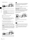
Using the camcorder as a feeder
To copy digitally from the camcorder to the VTR
without the editing function
Using an i.LINK cable (DV cable) to connect a digital
video cassette recorder with an i.LINK connector to the
camcorder, digital copy of video and audio can be carried
out.
Note
Note
1 75Ω coaxial
cable
PDW-F355/F355P
LMD-9050
liquid crystal display monitor
to VIDEO OUT connector
to SDI input connector
to SDI OUT
connector
to LINE A/B input
connector
2 75Ω coaxial cable
Note