


22
Location and Function of Parts
Chapter 1 Overview
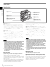
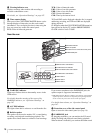
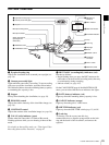
c Viewfinder front-to-back positioning knob
Loosen this knob to adjust the front-to-back position of the
viewfinder (see page 36).
d Lid of the disc compartment
This opens when the EJECT button on the top panel is
pressed. Press the side of the lid to close.
e Accessory fitting shoe
Attach an optional accessory such as a video light (see
page 39).
f Shoulder strap fitting
Attach the supplied shoulder strap (see page 38).
g Viewfinder left-to-right positioning ring
Loosen this ring to adjust the left-to-right position of the
viewfinder (see page 36).
h Viewfinder fitting shoe
Attach the supplied viewfinder.
i Fitting for optional microphone holder
Fit an optional CAC-12 Microphone Holder (see page 40).
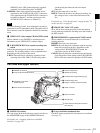
j LIGHT (video light) connector (2-pin, female)
A video light with a maximum power consumption of 50
W, such as the Anton Bauer Ultralight 2 or equivalent can
be connected (see page 39).
k MIC IN (microphone input) (+48 V) connector
(XLR type, 5-pin, female)
Connect the supplied stereo microphone to this connector.
The power (+48 V) is supplied via this connector.
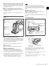
l Shoulder pad
Raise the shoulder pad fixing lever to adjust the position in
the front-to-rear direction. Adjust the position for
maximum convenience when operating the unit on your
shoulder.
For details of the adjustment, see “Adjusting the Shoulder
Pad Position” on page 38.
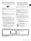
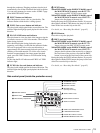
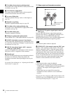
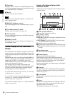
1 Video output and timecode connectors
a GENLOCK IN (genlock signal input) connector
(BNC type)
Input an SD or HD reference signal when applying a
genlock to the camera, or synchronizing timecode to an
external source. Use the GENLOCK page of the
MAINTENANCE menu to carry out phase adjustment of
the horizontal synchronization signal for genlock.
The subcarrier phase cannot be adjusted.
b VIDEO OUT (video output) connector (BNC type)
Outputs a video signal for a video monitor. The output
signal is composite or HD Y. When the output signal is
composite, setting menus, timecode, or shot data can be
superimposed on the camera output video depending on
the menu settings, and you can view them on the monitor
screen. To lock the timecode of an external device to the
timecode of this unit, connect the genlock signal input
connector of the external device to this connector.
• The subcarrier phase cannot be adjusted.
• Even when you are recording or playing back HD
23.98P signals, 23.98PsF signals are not output from this
connector. The output is 59.94i signals after 2-3
pulldown.
• Video signals are not output if the connection
destinations of these connectors are not terminated
properly.
You can select the composite or HD Y signal output on the
OUTPUT page of the OPERATION menu. For details, see
“Selecting the Output Signals” on page 141.
Note
Notes
GENLOCK
IN
VIDEO
OUT
TC
OUT
TC IN
2 VIDEO OUT connector
3 TC OUT connector
4 TC IN connector
1 GENLOCK IN connector