


Locations and Functions of Parts and Controls
30
Chapter 1 Overview
Before using this connector, you must set
ETHERNET/USB on the POWER SAVE page of
the OPERATION menu to “ENABL” (see page
212).
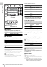
d (network) connector (RJ-45 type)
This is a 10BASE-T/100BASE-TX connector for
network connection.
Before using this connector, you must set
ETHERNET/USB on the POWER SAVE page of
the OPERATION menu to “ENABL” (see page
212).
CAUTION
For safety, do not connect the connector for peripheral
device wiring that might have excessive voltage to this
port. Follow the instructions for this port.
When you connect the network cable of the unit to
peripheral device, use a shielded-type cable to prevent
malfunction due to radiation noise.
e EARPHONE jack (stereo, minijack)
You can monitor the E-E sound during recording
and playback sound during playback. When an
alarm is indicated, you can hear the alarm sound
through the earphone. You can use this with the
EARPHONE jack on the front of the unit at the
same time. Plugging an earphone into the jack
automatically cuts off the built-in speaker.
You can select monaural or stereo on the AUDIO-
1 page of the MAINTENANCE menu.
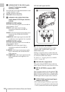
f LINE / AES/EBU / MIC selectors
These select the audio source of the audio input
signals input to the AUDIO IN CH1/CH2
connectors.
LINE: Line input audio equipment
AES/EBU: AES/EBU format audio signal
MIC: Microphone input
Note
When these switches are in the MIC position, and the
+48V/OFF switch is set to +48V, if you inadvertently
connect any audio device other than a microphone to the
AUDIO IN CH1/CH2 connectors, the device may be
damaged.
g +48V/OFF switches
Select either of the following positions for the
microphones to be connected.
+48V: For a microphone to use an external power
supply
OFF: For a microphone to use an internal power
supply
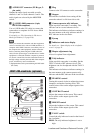
h REMOTE connector (8-pin)
Connect an RM-B150/B750 remote control unit,
which makes it possible to control the camcorder
remotely.
Note
Before connecting/disconnecting the Remote Control
Unit to/from the camcorder, be sure to turn off the
camcorder POWER switch.
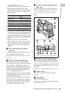
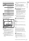
i SDI OUT 1 connector (BNC type)
Outputs an HDSDI or SDSDI signal (with
embedded audio). To switch between HDSDI and
SDSDI output, use the SDI OUT 1 SELECT item
on the OUTPUT 1 page of the OPERATION
menu.
j SDI OUT 2 connector (BNC type)
Outputs an HDSDI or SDSDI signal (with
embedded audio). To switch between HDSDI and
SDSDI output, use the SDI OUT 2 SELECT item
on the OUTPUT 1 page of the OPERATION
menu.
Setting menus, timecode, or shot data can be
superimposed on the camera output video
depending on the menu settings, and you can
view them on the monitor screen.
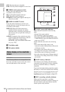
k AUDIO IN CH1/CH2 (audio channel-1
and channel-2 input) connectors (XLR
type, 3-pin, female)
These are audio input connectors for channels 1
and 2 to which you can connect audio equipment
or a microphone.
When the LINE / AES/EBU / MIC selector is set
to AES/EBU, the CH1 connector is used for
channel-1 and -2 inputs, and the CH2 connector,
for channel-3 and -4 inputs.
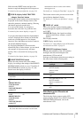
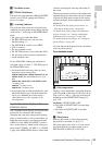
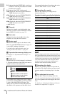
Device Enables
Windows USB
keyboard or mouse
Text input wth the on-screen
software keyboard (see page
124)
USB flash drive Recording of proxy data (see
page 104)
Loading of planning metadata
(see page 136)