


Locations and Functions of Parts and Controls
33
Chapter 1 Overview
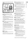
d Viewfinder screen
e VTR SAVE indicator
This indicator lights when the VDR SAVE/STBY
switch is set to SAVE, putting the VDR into
power save mode.
f ! (warning) indicator
This indicator lights when any of the following
conditions occurs with the corresponding item set
to ON on the ‘!’ LED page of the OPERATION
menu.
• The gain is set to other than 0 dB.
• The SHUTTER selector is not set to the
standard setting.
1),2)
• The WHITE BAL switch is set to PRST.
• ATW is enabled.
• The lens extender is used.
• The FILTER selector is set to other than ND:1.
• The reference value of auto iris adjustment is
not the standard value.
For the PDW-F800, lighting-up conditions of
each item can be set on the ‘!’ LED STD page of
the OPERATION menu.
1)The standard SHUTTER setting differs as follows,
depending on the recording format.
1080/50i, 1080/59.94i, 720/50P, 720/59.94P (SCAN
MODE: 59.9P): The SHUTTER selector is set to
OFF.
1080/23.98P, 720/59.94P (SCAN MODE: 23.9P):
1
/
48
shutter is ON.
1080/25P:
1
/
50
shutter is ON.
1080/29.97P:
1
/
60
shutter is ON.
2) For the PDW-F800, when SHUTTER SELECT on the
SHUTTER SELECT page of the MAINTENANCE
menu is set to DEGREE, the standard setting is
“SHUTTER selector: OFF”, regardless of the
recording format.
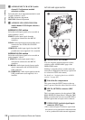
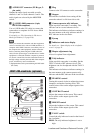
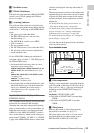
Layout of the status display on the
viewfinder screen
The viewfinder screen displays not only the video
picture but also characters and messages
indicating the camcorder settings and operating
status, a center marker, a safety zone marker, etc.
When the menu screen is not displayed and the
DISPLAY of the DISPLAY/ASPECT switch is
set to on, the items for which an ON setting was
made on the VF DISP 1, VF DISP 2, or VF DISP
3 page of the OPERATION menu or with related
switches are displayed at the top and bottom of
the screen.
The messages that give details of the settings and
adjustment progress and results can also be made
to appear for about three seconds while settings
are being changed, during adjustment, and after
adjustment.
For details about the display item selection, see
“Selecting the display items” on page 201.
For details about setting change and adjustment
progress messages, see “Change confirmation/
adjustment progress messages” on page 202.
For details about marker display, see “Setting the
marker display” on page 203.
All items that can be displayed on the viewfinder
screen are shown below.
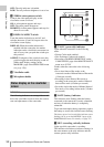
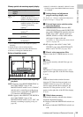
Top of viewfinder screen
a Color temperature
Displays a color temperature calculated from the
gain of R and B, in the range 0.0 K to 99.9 K (in
steps of 0.1 K). The +/– signs may be displayed
depending on the OFFSET WHT setting (see
page 212).
No display: OFFSET WHT is OFF
+: The value of OFFSET WHT is greater than
3200K.
–: The value of OFFSET WHT is less than
3200K.
b Video format
Indicates the format of video being currently
played back or recorded (see page 57).
The video aspect ratio (16:9 or 4:3) can also be
displayed when the recording format is set to
IMX 50, IMX 40, IMX 30, or DVCAM.
123 4 5 7689
0q
a
q
s
EX Z W
13.4
V
99 1 2
HD422 50 E0001:001/004 DC IN
59.9 i
[
30
]
CONT
FAN
13.9
35-30
K+
WHITE:NG
LEVEL TOO HIGH EXT
REC2 TCG 01:23:45:15 HDSDI
1 -
125
C
LOW LIGHT
5600
F1.718 35 30dB 1/ 2000
1
2
W:A