


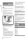

Preparing the Audio Input System
49
Chapter 2 Preparations
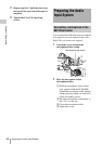
3 Set the AUDIO IN switch for the
channel to which you want to input
audio signal to WIRELESS (see page
28).
Notes
• When the XLR connection automatic detection
function is on, even if the AUDIO IN CH-1 or CH-2
switch is set to WIRELESS, the signal input to the
AUDIO IN CH1 or CH2 connector is automatically
selected when an audio cable is connected to the
AUDIO IN CH1 or CH2 connector. In such a case, set
REAR XLR AUTO to OFF on the AUDIO-1 page of
the MAINTENANCE menu. (The factory default
setting is OFF.)
• When the LINE / AES/EBU / MIC selector is set to
LINE or MIC, the audio signals recorded on audio
channels 3 and 4 are not affected by the XLR
automatic detection function. They are determined by
the settings of the AUDIO IN CH-3 and CH-4
switches.
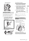
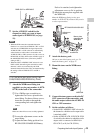
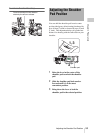
To fit the WRR-862 (when using a BP-
GL65/GL95/L60S/L80S Battery Pack)
1 Attach the WRR tuner fitting (not
supplied; service part number: A-8278-
057-B) to the back of the camcorder.
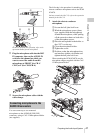
1 Use a Phillips type screwdriver to
tighten the four screws placed in the
tuner fitting. For three of these screws,
insert the screwdriver through the
corresponding hole and tighten the
screw.
Note
Make sure that all four screws are fully tightened.
2 Loosen the adjustment screws on the
tuner fitting.
3 Adjust the tuner fitting position for a
BP-GL65/GL95/L60S/L80S Battery
Pack to be attached, and tighten the
adjustment screws to fix its position.
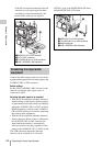
4 Attach the mount plate supplied with
the WRR-862.
About the WRR tuner fitting (service part
number: A-8278-057-B), contact a Sony service
or sales representative.
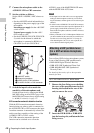
2 Attach the battery pack.
On how to attach the battery pack, see “To
attach the battery pack” on page 37.
3 Mount the tuner on the WRR tuner
fitting.
4 Connect the tuner power cord to the DC
OUT connector of the camcorder, and
the audio output cable to the AUDIO IN
CH1 or CH2 connector.
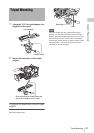
5 Set the switches as follows.
• Set the LINE / AES/EBU / MIC selector for
the channel to which the audio output cable
is attached to MIC.
• Set the AUDIO IN (CH-1/CH-2/CH-3/CH-
4) switch for the channel to which the audio
output cable is connected to REAR (for
CH-1/CH-2) or R (for CH-3/CH-4).
DWR-S01D or WRR-855S
BP-GL65/GL95/L60S/L80S
Adjustment
screws
Mount plate
(supplied with
WRR-862)
Phillips type
screwdriver
WRR-862