First use
2.3 Switch on the system
2.3.1 Switching on
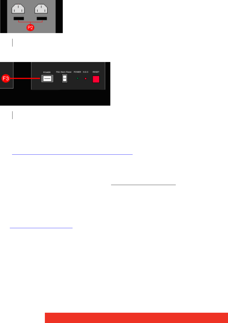
• Ensure that both Power Supply Units at the rear side are switched on.
• Press and release the main power switch at the front side.
2.3.2 Setup procedure (only first use)
• The BIOS and boot messages will appear on the Control Screen that is plugged into the
VGA output socket of the ECU-100 (see S4 on figure on “Rear View” figures in paragraph
“Overview of preconfigured ECU hardware configurations
”)
• When the system has booted the Windows® “Splash Screen” is displayed on the Con-
trol Screen.
• Complete the Windows® setup procedure to select language, user account details and
computer name. You will be prompted for the Operating System Product Key
, this is
located on the Operating System CD case in the Accessories pack.
• Once Windows® has been set up, the Control Screen and Display Wall will open into a
Windows® desktop.
• The ECU -100 has pre-configured factory settings for the wall layout and screen resolu-
tion. These settings can be changed using the Wall Configuration tab accessed from the
Display properties dialog box
.
P2 Main Power Switches at the rear side of the ECU-100
F3 Main power switch at the front side of the ECU-100
