


90 Hardware possibilities
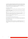
5.1.5 Rear view ECU-100 GVD-1600808
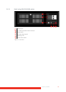
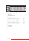
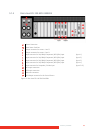
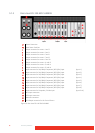
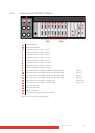
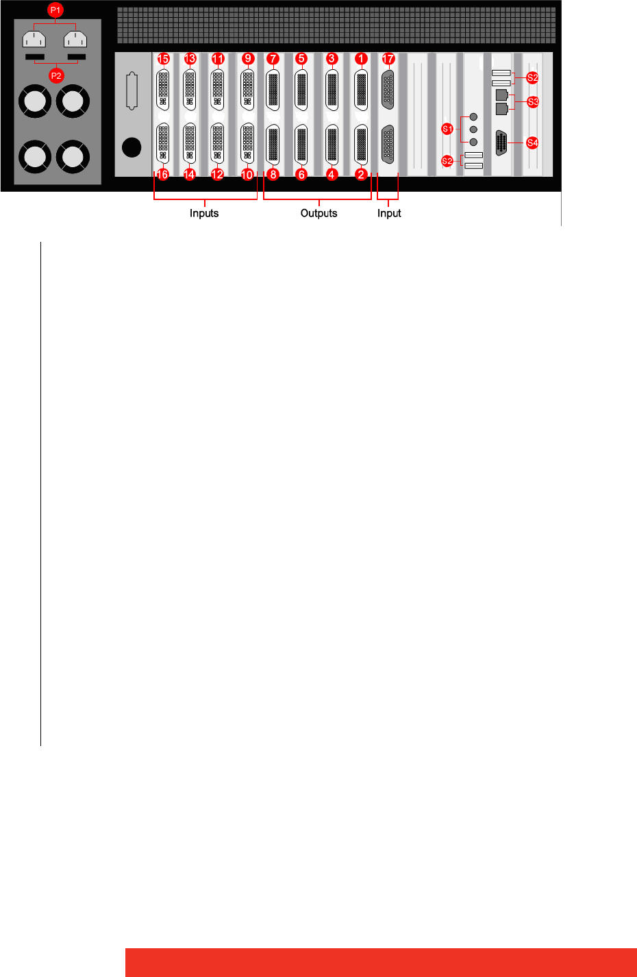
Figure 20: Rear view ECU-100 GVD-1600808
P1 Power Connectors
P2 Main Power Switches
1 Output connector for screens 1 and 2
2 Output connector for screens 3 and 4
3 Output connector for screens 5 and 6
4 Output connector for screens 7 and 8
5 Output connector for screens 9 and 10
6 Output connector for screens 11 and 12
7 Output connector for screens 13 and 14
8 Output connector for screens 15 and 16
9 Input connector for DVI/HDMI/Component/RGB (VGA) input (Input 1)
10 Input connector for DVI/HDMI/Component/RGB (VGA) input (Input 2)
11 Input connector for DVI/HDMI/Component/RGB (VGA) input (Input 3)
12 Input connector for DVI/HDMI/Component/RGB (VGA) input (Input 4)
13 Input connector for DVI/HDMI/Component/RGB (VGA) input (Input 5)
14 Input connector for DVI/HDMI/Component/RGB (VGA) input (Input 6)
15 Input connector for DVI/HDMI/Component/RGB (VGA) input (Input 7)
16 Input connector for DVI/HDMI/Component/RGB (VGA) input (Input 8)
17 Input connector for Composite/S-Video input (Input 9–16)
S1 Aux Input connectors
S2 USB Input connectors
S3 Network connectors
S4 VGA Output connector for the Control Screen