


English _41
● INSTALLATION & CONNECTION
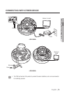
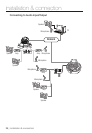
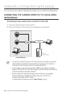
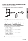
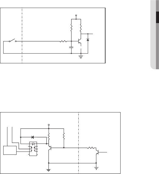
To connect the external sensor
Connect one strand of each signal line (2-strand) of the sensors to the [ALARM IN] port,
and connect the other strand to the [GND] port.
Alarm In Wiring Diagram
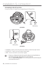
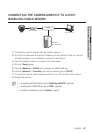
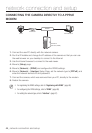
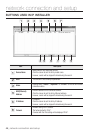
To connect the alarm out
If devices (e.g., flashing light and siren) that exceed the voltage and current specifications
are connected by using the open collector method, it may cause malfunction.
Refer to the alarm out connection diagram below when connecting devices that exceed the
voltage and current specifications.
Alarm Out Wiring Diagram
Sensor
GND
RESISTORALARM IN (5mA SINK)
RESISTOR RESISTOR
VCC_3.3V
DIODE
GND
MLCC
TRANSISTOR
External
connection
Inside of the camera
Warning lamp /
Siren power
Warning lamp /
Siren
(
-
) (
+
)
ALARM OUT (12VDC 20mA MAX)
RESISTOR 10K ohm
DIODE
RELAY
DC 5V or 3.3V
TRANSISTOR
GND
GND
TRANSISTOR
External connection Inside of the camera
GND
RESISTOR