


90 Chapter 4 Viewfinder Screen Indications and Menus
Chapter 4 Viewfinder Screen Indications and Menus
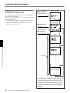
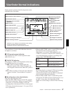
w; Filter setting indication
This shows the setting of the FILTER control.
wa Clock indication
The clock indication is shown in one of the following
ways (according to the CLOCK IND setting of OFF,
CAM, or BARS in advanced menu page 8). (See page
105.)
OFF: Not displayed.
CAM: Always displayed.
BARS: Displayed whenever color bars are
displayed.
If the clock indication is displayed during recording, it
is recorded onto the image.
ws Voltage/error indication
When power in the camcorder’s batteries grows low
and the error message LOW BATT appears, the
voltage is displayed. When power is normal, you can
view the voltage by pressing the MENU switch up to
the STATUS side and holding it there to view the
status indication.
An error message is displayed when an abnormality
has been detected by the auto diagnostic function
(page 97). If there is a voltage drop below 11.3 V DC
and an error has been detected, the low voltage
indication alternates at one-second intervals with the
error indication.
If an error message appears, contact your Sony dealer.
If using an Anton Bauer Intelligent Battery System
The remaining battery capacity is shown as a
percentage.
wd Shutter setting indication
When the SHUTTER switch has been set to ON, the
basic menu page 1 setting for the item SHUTTER
(shutter speed, CLS frequency, EVS) is displayed here.
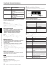
Status Indications
If you set the MENU switch to STATUS while a menu
is being displayed, the camcorder’s current setting
status will be shown in this display area.
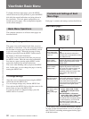
a) When both the DCC+ and DynaLatitude
functions are set to OFF
Display
Description
WHITE White balance adjustment method
selection (PRE/A/B) and color
temperature during auto white
balance adjustment
A.IRIS
SETUP FILE Setting of the SETUP switch (page
25)
DCC+ or DL
Iris adjustment method selection
(STD/SPOT L/BACK L)
For DCC+ indication: ON with the
OUTPUT/DL/DCC+ switch set to
CAM/DCC+ (DCC+ ON), and OFF
with the switch set to CAM/DL and DL
in advanced menu page 2 (page 100)
set to OFF (both DCC+ and
DynaLatitude OFF).
For DL indication: When setting the
OUTPUT/DL/DCC+ switch to DL and
DL in advanced menu page 2 to OFF
(DynaLatitude OFF), LOW, STD or
HIGH is displayed according to DL
LEV setting in basic menu page 2
(page 93).
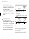
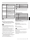
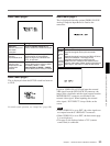
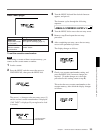
Indication Filter setting
3200 1 (3200K)
56ND 2 (5600K +
1
/8ND)
5600 3 (5600K)
56ND 4 (5600K +
1
/64ND)
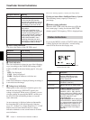
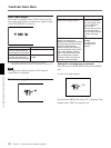
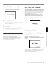
Viewfinder Normal Indications
Example indication Meaning
18 dB Gain setting is 18 dB.
DPR 18 dB The DPR function is enabled.
In this case the DPR function
approximately doubles the gain (an
increase of 6 dB) over the current
gain setting (in this case 18 dB).
HYPER The HYPER GAIN switch is in the
ON position.
In this case, regardless of the
current gain setting, the hyper gain
function increase the gain by a
factor of about 60 with respect to 0
dB (to 36 dB). In the case of the
DSR-570WS/570WSP, menu
switching allows the gain to be
increased by a factor of about 120
with respect to 0 dB (to 42 dB).