


4-98
DVW-790WS/709WS/707 P2V1
DVW-790WSP/709WSP/707P P2V1
4-2. Parts Replacement
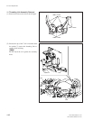
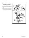
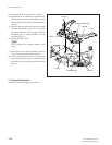
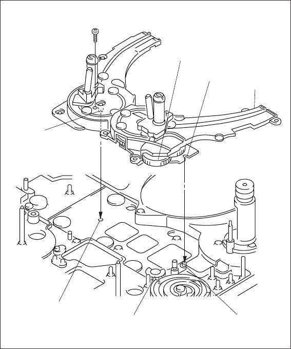
(3) Put the tip of the T rail under the catcher T.
(4) Align the boss (A) and the hole, and the notch
(B) and the boss as shown in the figure. Attach
the threading link assembly to the mechanical
chassis.
(5) If the ST driving middle gear does not engage
with the intermittent gear, turn the manual
eject gear clockwise till they engage. (The in-
termittent gear is turned together with the
manual eject gear.)
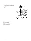
(6) Tighten the nine screws.
n
Do not scratch the stationary heads by the
driver.
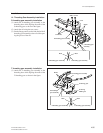
(7) Remove the screw (2x10) attached in the step
16 (1) from the threading link assembly.
(8) If the intermittent gear turned in the step (5),
turn the manual eject knob counterclockwise
and return the cam gear to the position of the
step (2).
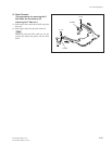
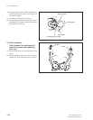
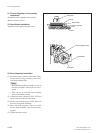
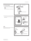
17. Catcher S Installation
Attach the catcher S using the three screws.
M 2x10
Boss A
Boss B
Hole A
Intermittent
g
ear
ST driving middle gear
Notch B
T rail