


7-6
DVW-790WS/709WS/707
DVW-790WSP/709WSP/707P P2V1
7-3. AD Clock Phase Adjustment
16:9 mode
Note
Conduct this check when the CCD block or DCP-17 board
is only replaced.
Preparation
. On the setup menu, set as follows.
PAGE : S12*FUNCTON 1/2
ITEM : TEST OUT → ENC
. OUTPUT/DCC switch (inside panel) → CAM/ON
. WHITE BAL switch (inside panel) → A
. AUTO W/B BAL switch (front panel) → WHT
(Perform the automatic white balance adjustment.)
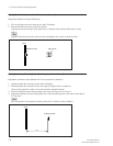
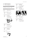
. Shoot a multiburst chart (4:3) in the underscan’s hori-
zontal picture frame.
Test point : VIDEO OUT connector
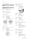
setting point : 1 Lens IRIS
Spec. : A (white level) = 90 ± 2 IRE (NTSC)
A = 630 ±10 mV (PAL)
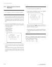
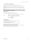
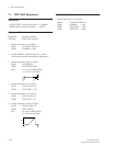
. Pan the camera so that the 5 MHz signal portion of the
multiburst chart is positioned at the center of the monitor
screen. (Do not change the camera zoom.)
Chart frame
Underscanned monitor
Frame
A
5 MHz
(Waveform monitor)
Adjustment Procedure
Equipment : Waveform monitor
Test point : VIDEO OUT connector
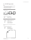
1. Select the 16:9 mode.
PAGE : S14*WIDE SCREEN
ITEM : 16:9/4:3 MODE → 16:9
2. On the setup menu, adjust as follows.
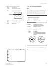
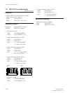
PAGE : S54*AD ADJ.
ITEM : AD CLOCK PHASE
Spec. : Maximize the 5 MHz signal portion.
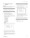
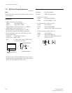
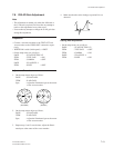
3. On the setup menu, adjust as follows.
PAGE : S54*AD ADJ.
ITEM : R/B CLOCK PHASE
Spec. : Adjust the 5 MHz signal portion to
nearly horizontal.
5 MHz
NG OK
7-3. AD Clock Phase Adjustment