2-1
DVW-790WS/709WS/707
DVW-790WSP/709WSP/707P P2V1
Section 2
Setup Menu
This section describes the service mode that is part of the Setup Menu which appears on the viewfinder screen.
For the VTR menu, refer to the Maintenance Manual, Part 1, Section 3-2.
2-1. Service Mode
The circuit boards that are supplied as repair parts have already been adjusted before shipment from the
factory. However, the adjustment values somewhat differ for each product. After replacing any of the
circuit boards relating to the video signal of the camera, use the service mode to perform accurate adjust-
ment.
Data Structure
Data structure of the setup menu is described as shown below.
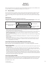
Setup values of the setup menu = Fixed data (absolute value) + Service mode setup value (relative value)
+ Engineer mode setup value (relative value) + User mode setup value (relative value)
. When any item is adjusted using the service mode, the adjustment value of that item in the engineer
mode and that in the user mode are returned to 0.
. The fixed data has been stored in IC15 on the DR-387 board, IC140 on the DCP-17 board and IC18 on
the ES-23 board respectively. The set values in the user, engineer and service modes are stored in
IC123 on the DCP-17 board.
. The set values in the user, engineer and service modes have been set to 0 when the unit is shipped from
the factory.
. Refer to the Operation Manual and Maintenance Manual, Part 1, Section 3 for the user mode and the
engineer mode.
. When the RM-B150/P9 remote control is connected to operate the system externally, there are some
items whose set values cannot be changed or to which set values are not reflected. Refer to Section
2-1-3, “Setup Menu List” for details.
How to Return the Set Values of Each Mode to the Default Values
The set values of each mode can be returned to the default values using the setup menu.
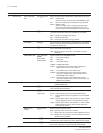
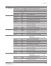
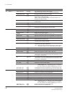
Refer to the items on the DATA RESET page in Section “2-1-2 Contents of Setup Menu” for details.
About the Setup Card
. When a setting is saved in a setup card, the set value in the user mode and that in the engineer mode are
stored separately.
. The fixed data differs for each product. When the same setup card is used for the camera adjustment
using the service mode before and after replacing the board or for adjusting multiple cameras, the same
fixed data and the same setup data in the service mode can be obtained.
Therefore, the desired value should be set using a typical camera as the reference camera in both the
user mode and engineer mode, and the value should be saved in a setup card. When a board is replaced
or other cameras are to be matched, adjust the camera in the service mode first, then download the data
that has been saved in the setup card, to the camera.
How to Enter the Service Mode
When the MENU/ON/OFF switch has been set to the ON position during normal operation after the main
power is turned on, the camera enters the user mode. To make the camera enter the service mode, set the
following switch, turn on the main power and then set the MENU/ON/OFF switch to the ON position.
S4-1/DCP-17 board → ON
Fixed data (absolute value)
User mode data (relative value)
Engineer mode data (relative value)
Service mode data (relative value)
Setup values of the setup menu
(adjustment value)
Stored in setup card
Default data when shipped
from factory


