


4-114
DVW-790WS/709WS/707 P2V1
DVW-790WSP/709WSP/707P P2V1
4-2. Parts Replacement
Installation
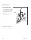
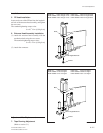
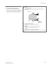
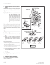
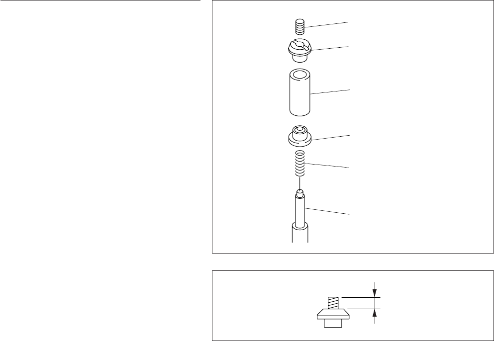
2. Tape Guide Installation
(1) Pass the compression coil spring through the
guide shaft.
(2) Pass the lower flange through the guide shaft.
(3) Pass the roller assembly through the guide
shaft.
n
The tension regulator (S4) guide roller is ta-
pered. Attach with the thicker side the top.
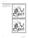
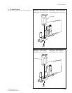
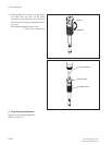
(4) Screw in the upper flange until it touches the
guide shaft.
n
If the upper flange or locking screw has been re-
placed, perform step (4) with the locking screw
protruding out of the upper flange surface about 2
mm.
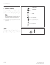
Locking screw
Upper flange
Roller
Lower flange
Compression spring
Guide shaft
2 mm