


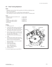
5-11
DVW-790WS/709WS/707
DVW-790WSP/709WSP/707P P2V1
5-2. Video Tracking Adjustment
Notes
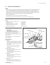
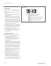
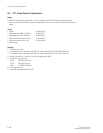
. Tighten the screws at the top of the tape guides to the following tightening torque.
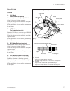
9 x 10
_2
N.m (0.9 kgf.cm)
. After this adjustment, be sure to check the tape running adjustment.
After checking, put a locking compound to the screws at the top of each tape guide.
Tools
. Tape guide adjustment screwdriver (45) : J-6322-420-B
. Inspection mirror : J-6080-840-A
. TP tool : J-6420-910-A
. Alignment tape, ZR2-1 (NTSC) : 8-960-073-11
. Alignment tape, ZR2-1P (PAL) : 8-960-073-61
. Oscilloscope
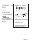
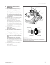
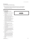
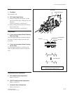
Switch S1
Switch S4
Switch S1
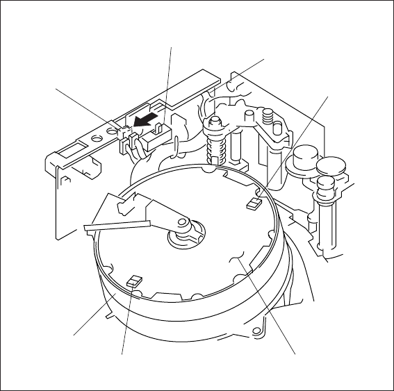
HN-260 board
UDR-9 board
Switch S2
Drum assembly
5-2. Video Tracking Adjustment
Setting
1. Turn the power off.
2. Connect the 8-pin connector of the TP tool to
the connector CN7 on the HN-260 board.
3. Connect the 5-pin connector of the TP tool to
the connector CN3 on the CTL-10 board.
4. Set the all four switches of switches S1 and
S2 on the UDR-9 board which is attached to
the upper drum to TEST (ON).
5. Set the switch S4 on the HN-260 board to
TEST.
6. Disconnect the connector that comes from
the slip ring and connect the connector of the
harness to CN9 on the HN-260 board.
7. Set the switches S1-1 and S1-2 on the HN-
260 board to OFF.
8. Connect an oscilloscope.
CH-1 : REC RF A/TP tool
CH-2 : REC RF E/TP tool
TRIG : SV REF CF/TP tool
9. Turn the power on.
10. Insert the alignment tape cassette ZR2-1P.