


Locations and Functions of Parts and Controls
28
Chapter 1 Overview
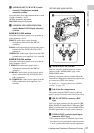
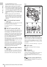
Use the GENLOCK page of the
MAINTENANCE menu to adjust the genlock
H-phase (phase of horizontal sync signal).
• This connector also inputs a return video signal.
You can display the HD-Y (1080i) signal in the
viewfinder screen while holding the RET button
down with RETURN VIDEO set to ON on the
ASSIGNABLE SW page of the OPERATION
menu.
• Input an external video signal. When the
optional CBK-SC02 Analog Composite Input
Board is installed, the unit can record analog
composite video signals that are input to this
connector.
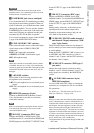
e TC IN (timecode input) connector
(BNC type)
To apply an external lock to the timecode of this
unit, input the reference timecode.
For details of timecode, see “Setting the timecode”
on page 68.
f TEST OUT connector (BNC type)
This connector outputs the video signal for a
video monitor. The output signal can be selected
from composite video, HD-Y, R, G, B, and a
composite video signal like that displayed in the
LCD monitor. To switch output signals, use the
TEST OUT SELECT item on the OUTPUT 1
page of the OPERATION menu.
If the output signal is set to one of R, G, or B, then
this setting changes to HD-Y when the camcorder
is powered off and on again.
Depending on menu settings, menus, timecode,
and shot data can be superimposed on the image
on the monitor. This connector can also be used to
synchronize the timecode of an external VTR
with the timecode of the camcorder.
g TC OUT (timecode output) connector
(BNC type)
To lock the timecode of an external VTR to the
timecode of this unit, connect this connector to
the external VTR’s timecode input connector.
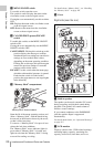
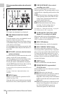
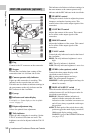
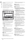
Rear
a TALLY (back tally) indicator (red)
Lights up during recording. It will not light if the
TALLY switch is set to OFF. This indicator also
flashes to indicate warnings (see page 21) in the
same manner as the REC/TALLY indicator in the
viewfinder.
For details, see “Operation Warnings” on page 215.
b TALLY switch
Set to ON to activate the TALLY indicator
function.
c USB connector
This is a USB 2.0 connector.
Connect a Windows USB keyboard or mouse (see
page 110), or a USB flash drive to access
planning metadata stored on the drive (see page
121).
d (network) connector (RJ-45 type)
This is a 10BASE-T/100BASE-TX connector for
network connection.
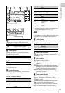
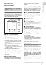
SDI OUT
DC OUT
12V
0.5A
LINE
SUPER
MIC
48V
OFF
CH1
1/2
SDI OUT
DC
IN
AES/EBU
AUDIO IN
AUDIO OUT
CH2
3/4
LINE MIC
48V
OFF
AES/EBU
89 0 qa qs qd
1
2
3
4
567