


Locations and Functions of Parts and Controls
33
Chapter 1 Overview
i Controlling external device
Appears when HDSDI REMOTE I/F in the CAM
CONFIG 1 page of the MAINTENANCE menu
is set to CHARA, and this unit is controlling
recoding by an external device connected to the
SDI OUT 1/2 connectors (HDSDI output).
1)
1)SDI OUT 1 SELECT or SDI OUT 2 SELECT on the
OUTPUT 1 page of the OPERATION menu must be
set to HDSDI.
j Electric color temperature filter
Appears when the CC 5600K function is set to
ON.
k Filter
Indicates the currently selected filter type (see
page 17).
When the function that switches between
electrical CC filters has been assigned to an
ASSIGN switch (see page 59), and when a
remote control unit has been connected, the
electrical CC filter position (A, B, C, or D)
appears to the right side of the ND filter display
(1 to 4).
l White balance memory
Indicates the currently selected white balance
automatic adjustment memory.
A: Displayed when the WHITE BAL switch is set
to A.
B: Displayed when the WHITE BAL switch is set
to B.
P: Displayed when the WHITE BAL switch is set
to PRST or when the preset button on an RM-
B150 has been pushed.
T: Displayed when ATW is being used.
3200: Displayed when the COLOR TEMP SW
3200K function is set to ON.
4300: Displayed when the COLOR TEMP SW
4300K function is set to ON.
5600: Displayed when the COLOR TEMP SW
5600K function is set to ON.
6300: Displayed when the COLOR TEMP SW
6300K function is set to ON.
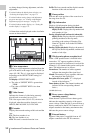
m Timecode
Indicates the elapsed recording/playback time,
timecode, user bits or other information selected
by the DISPLAY switch (see page 22).
n Gain value
Indicates the gain value (in dB) of the video
amplifier, as set by the GAIN selector.
o Shutter speed
Indicates the shutter speed or the shutter mode.
However, if the SHUTTER selector (see page 17)
is set to OFF, nothing is displayed.
For details of the displayed shutter speed, see
“Setting the Electronic Shutter” on page 60.
p Operation/alarm message display area
For details, see “Operation/alarm messages” on
page 218.
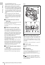
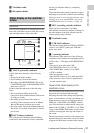
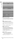
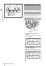
q Audio level
Indicates the level of audio channel 1 and channel
2. The peak indication of the VDR level meter is
related as follows to the audio level.
The segment colors change from gray to white at
or above the AU REF LEVEL set on the AUDIO-
2 page of the MAINTENANCE menu. This
setting does not affect the relationship between
the number of lit segments and the audio levels.
The example in the above figure shows the colors
when AU REF LEVEL is set to –20 dB.
r Remaining disc capacity
Indicates the remaining recording time (in
minutes) of the disc.
-52 -28 -20 -12 -8(dB)
1
2
3
1Audio channel 1 level indicator
2Audio channel 2 level indicator
3VDR level meter indicator