


16
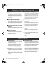
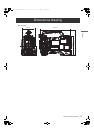
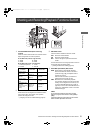
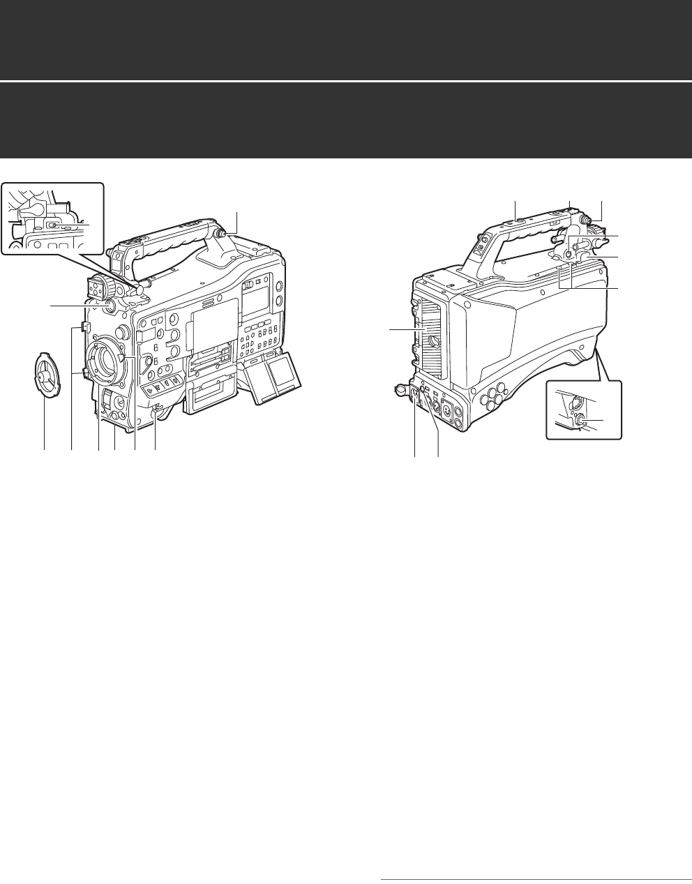
Parts and their Functions: Power Supply and Accessory Mounting Section
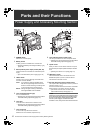
1. POWER switch
Used to turn on/off the power.
2. Battery mount
A battery pack from Anton/Bauer is mounted here.
> [Mounting the Battery and Setting the Battery Type]
(page 109)
3. DC IN (external power input) socket (XLR, 4P)
camera-recorder is connected to an external DC power
supply.
> [Use of the external DC power supply] (page 110)
4. LIGHT switch
Choose a way to turn the video light connected to the
16.LIGHT connector ON/OFF.
AUTO: If you leave the video light POWER switch
ON, then the light will light at the same time
that this unit starts recording, and the light will
go out at the same time recording stops.
MANUAL
: The light will light according to whether the
video light POWER switch is ON/OFF.
5. Lens mount (bayonet 2/3-type)
The lens is attached here.
> [Mounting the Lens and Performing the Flange Back
and White Shading Adjustments] (page 111)
6. Lens lever
Lower this lever to lock the lens to the lens mount.
> [Mounting the Lens and Performing the Flange Back
and White Shading Adjustments] (page 111)
7. Lens mount cap
To remove the cap, raise the 6. lens lever.
When the lens is not mounted, replace the cap.
8. Lens cable/microphone cable clamp
This clamp secures the lens and microphone cables.
> [Mounting the Lens and Performing the Flange Back
and White Shading Adjustments] (page 111)
9. Tripod mount
When you want to mount camera-recorder on a tripod,
the optional tripod adapter (SHAN-TM700) is attached
here.
> [Mounting the Camera on a Tripod] (page 115)
10.LENS jack (12-pin)
The lens connection cord is connected here. For a
detailed description of your lens, see the relevant
manufacturer’s instruction manual.
11.DC OUT (DC power supply) output socket
This output socket is designed for 12-VDC. It provides a
maximum current of 1.5 A.
Connect an external switch to this socket to control REC
starts and stops or an LED for use as a tally lamp.
> [Connection of the DC OUT connector and the
external REC strat/stop switch] (page 117)
Note
Confirm the pin arrangements of the DC output connector
of the external DC power supply and the DC IN socket on
the unit, and connect the proper polarities to each other.
If the 12 V power supply is connected to the GND
connector in error, it may cause a fire or failure of the unit.
16
4
87 5
14
12
9
10
2
3
11
15
14
17
18
13
16
Parts and their Functions
Power Supply and Accessory Mounting Section
AJ-HPX3100G(VQT3A79)_E.book 16 ページ 2010年9月17日 金曜日 午後9時21分