


88
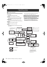
Adjustments and Settings for Recording : Selection of video output signals
The unit employs the SDI OUT connector and the MON OUT connector as connectors for outputting video signals.
The type of output signal from the SDI OUT connector is in
accordance with the SYSTEM MODE item. Additionally, the
signal output from the SDI OUT connector is switched from
the SDI OUT MODE item.
The SYSTEM MODE can be selected from the <SYSTEM
MODE> screen on the SYSTEM SETTING page, and the
SDI OUT MODE can be selected from the <OUTPUT SEL>
screen on the SYSTEM SETTING page.
Set the characters to be superimposed on the signals output
from the SDI OUT connector in the OUTPUT ITEM and SDI
OUT CHAR items. Items can be selected from the
<OUTPUT SEL> screen on the SYSTEM SETTING page.
Selection of video output signals
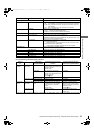
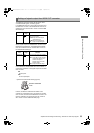
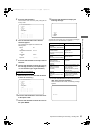
Settings of signals output from SDI OUT connector
Item
Variable
range
Remarks
SDI OUT MODE MEM
CAM
MEM: During EE such as recording,
video images taken by the
camera are output. Meanwhile,
signals on the P2 card are
output during playback.
CAM: Camera images are output at
all times.
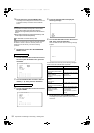
Item
Variable
range
Remarks
OUTPUT ITEM MENU
ONLY
TC
STATUS
Set the characters to be
superimposed on the output signals
from the VIDEO OUT connector.
MENU ONLY:
The menu screen is superimposed
only when the menu is accessed.
This normally displays nothing.
TC:
Time codes are superimposed
(when the menu is accessed, the
menu screen is superimposed.)
STATUS:
The characters that are the same
as the characters superimposed in
the viewfinder screen are
superimposed.
(When the menu is accessed, the
menu screen is superimposed.)
SDI OUT CHAR OFF
ON
Select whether to superimpose
characters on the image output from
the SDI OUT connector.
OFF:Do not superimpose.
ON: Superimpose.
Note
The content of the superimposed
characters is the same as that
superimposed on video output from
the MON OUT connector
AJ-HPX3100G(VQT3A79)_E.book 88 ページ 2010年9月17日 金曜日 午後9時21分