


82
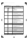
Adjustments and Settings for Recording : Viewfinder Screen Status Displays
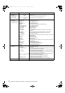
Displays in mode check only
Display screens and menu options Status when displayed
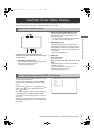
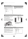
!LED screen
Displays menu options that become !LED lighting factors.
z Indications selected through the menu option !LED are marked with [ ! ].
z Indications which may activate the !LED are marked with [ ].
GAIN (0 dB)
DS.GAIN
SHUTTER
WHITE PRE.
EXTENDER
B.GAMMA
MATRIX
COLOR COR.
FILTER
AT W
Gain status
DS. GAIN value
Shutter status
White balance status
Extender status (EX2 or OFF)
BLACK GAMMA status (ON or OFF)
MATRIX status (A, B, or OFF)
Color correction status (ON or OFF)
Filter status
ATW status
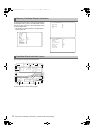
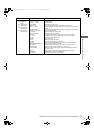
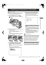
FUNCTION screen Displays video output status and recording media information.
SDI OUT
OUTPUT
TYPE
CHAR
Displays status of signals output from the SDI OUT connector
Displays MEM/CAM status displayed with the SDI OUT MODE menu option.
You can select the SDI OUT MODE menu option from the <OUTPUT SEL>
screen of the SYSTEM SETTING page.
Displays format of signals output from the SDI OUT connector with HD-SDI/SD-SDI.
Displays superimposition status of characters selected with the SDI OUT CHAR
menu option as ON/OFF. You can select the SDI OUT CHAR menu option from
the <OUTPUT SEL> screen of the SYSTEM SETTING page.
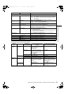
MON OUT
OUTPUT
SELECT
CHAR
Displays status of signals output from the MON OUT connector
Displays status of MEM/CAM selected with the MONITOR OUT MODE menu
option. The MONITOR OUT MODE item can be selected from the <OUTPUT
SEL> screen on the SYSTEM SETTING page.
Displays signal format set with the MONITOR OUT menu option as HD-SDI/
SD-SDI/VBS. The MONITOR OUT item can be selected from the <OUTPUT
SEL> screen on the SYSTEM SETTING page.
Displays the position of the MON OUT CHARATER switch as ON/OFF.
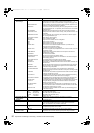
P2CARD STATUS
TOTAL
SLOT1
SLOT2
Displays the status of a P2 card inserted into the P2 card slot, and total space
and remaining space for recording.
The card status is indicated as:
ACTIVE/ACCESSING/INFO READING/FULL/PROTECTED/
NOT SUPPORTED/FORMAT ERROR/NO CARD
> [P2 CARD ACCESS LED and Status of P2 cards] (page 33).
Displays the total space and remaining space for recording of a P2 card
inserted into the P2 card slot 1 and 2.
Displays the status of a P2 card inserted into the P2 card slot 1, and total space
and remaining space for recording.
Displays the status of a P2 card inserted into the P2 card slot 2, and total space
and remaining space for recording.
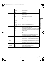
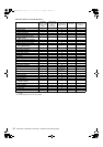
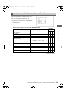
AUDIO screen Displays audio settings and selection status of each recording channel
SAMPLE RES Displays the number of audio recording bits.
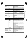
MIC POWER (MENU)
FRONT
REAR
Displays menu setting status for power provided to the microphone.
Displays status of power supplied to the front microphone, selected with the FRONT
MIC POWER menu option, as ON/OFF. You can select the FRONT MIC POWER
menu option from the <MIC/AUDIO> screen of the MAIN OPERATION page.
Displays whether the rear AUDIO IN connector is set to not supply power to the
microphone with the REAR MIC POWER menu option.
OFF: power is not supplied.
ON: supplies power when the switch is at MIC +48 V ON.
VR SELECT
VR SELECT Displays whether the audio level adjustment knob is selected to enable
either CH1/2 or CH3/4 with the VR SELECT menu option. You can select the VR
SELECT menu option from the <MIC/AUDIO> screen of the MAIN OPERATION page.
LEVEL CH1/2/3/4 Displays the recording level adjustment method selected for each channel.
VR: manual adjustment with the adjustment knob
MENU:manual adjustment with the menu LVL CONTROL CH# menu option
(# is the channel number)
AUTO:automatic adjustment
F.VR CH1/2/3/4
Displays with ON/OFF whether the F.AUDIO LEVEL control is enabled for channels
to which VR (manual adjustment with the adjustment knob) is selected above.
R.XLR CH1/2/3/4
Displays with ON/OFF the selection status of the REAR XLR AUTO CH1/2 and
REAR XLR AUTO CH3/4 menu options that automatically select rear input when a
connector is connected to the rear AUDIO IN XLR connector. You can select each
menu option from the <MIC/AUDIO> screen of the MAIN OPERATION page.
A. IN CH1/2/3/4
Displays the input status of each channel as FRONT (front)/REAR (rear)/W.L. (wireless).
METER CH1/2/3/4 Displays the recording level of each channel.
AJ-HPX3100G(VQT3A79)_E.book 82 ページ 2010年9月17日 金曜日 午後9時21分