


Chapter 7 Menu Displays and Detailed Settings
112
7-2 Status Display on the Viewfinder Screen
7-2 Status Display on
the Viewfinder
Screen
The viewfinder screen displays not only the video picture
but also characters and messages indicating the camcorder
settings and operating status, a center marker, a safety zone
marker, etc.
When the MENU ON/OFF switch is set to OFF and the
DISPLAY switch is set to ON, the items for which an
“ON” setting was made in the VF DISP1 page of the
USER menu or with related switches are displayed at the
top and bottom of the screen. The messages that give
details of the settings and adjustment progress and results
can also be made to appear for about 3 seconds while
settings are being changed, during adjustment, and after
adjustment.
For information about the display item selection, ssee 7-2-
2 “Selecting the Display Items” on page 114. For
information about setting change and adjustment progress
messages, see 7-2-3 “Display Modes and Setting Change
Confirmation/Adjustment Progress Messages” on page
115. For information about marker display, see 7-2-4
“Setting the Marker Display” on page 116.
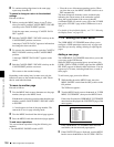
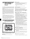
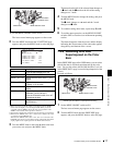
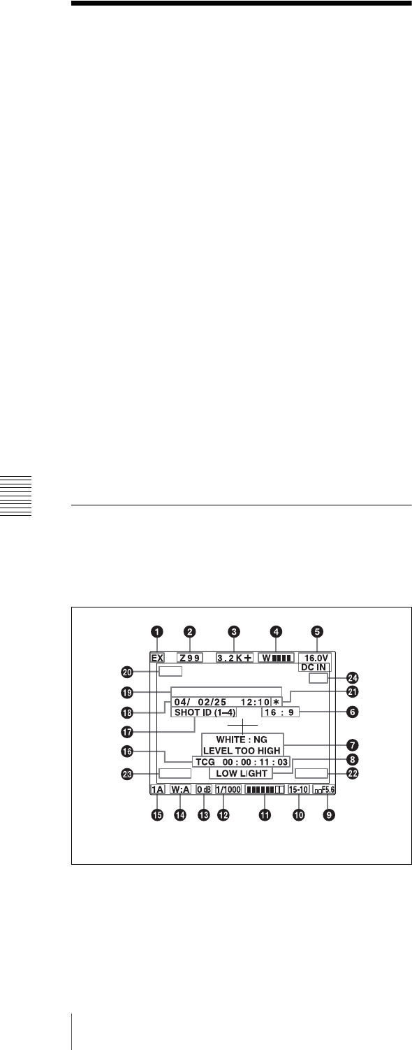
7-2-1 Layout of the Status Display
on the Viewfinder Screen
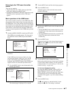
All items that can be displayed on the viewfinder screen
are shown below.
Status display on the viewfinder
a Extender
“EX” is displayed when a lens extender is used.
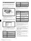
b Zoom position
This indicator appears only when you use a lens that has a
zoom position display function. It indicates the
approximate position of the variator
1)
of the zoom lens,
between wide angle and telephoto.
1) Variator
A group of lenses that are moved to adjust the focal length.
c Color temperature
This indicates the currently selected color temperature.
d UHF wireless microphone reception level
This indicates reception level of the wireless microphone
when the UHF wireless microphone is attached, using four
x which appear at the right of “W”. When four x are lit,
the receiving condition is good.
e DC IN / battery voltage or remaining capacity
This shows the battery voltage or remaining capacity of an
internal battery pack.
When the power is supplied from an AC adaptor connected
to the DC IN connector, “DC IN” appears.
When the DISP BATT REMAIN item is set to “INT” on
the VF DISP 2 page of the USER menu, the battery voltage
is not indicated. However, when the Anton Bauer
intelligent battery system or the BP-IL75/GL95/M100
battery pack is used, the remaining battery capacity is
automatically detected and indicated as a percentage even
when the DISP BATT REMAIN item is set to “OFF”. The
indicated value changes in steps of 10 %.
• Until the remaining battery capacity is reduced to 40 %,
the indications MAX, 90 %, 80 %...40 % are displayed
for three seconds in the viewfinder each time the
remaining battery capacity reduces by 10 %.
• When the remaining battery capacity is less than 40 %,
the indication is displayed all the time.
• When the remaining battery capacity is less than 10 %
1)
,
the the indication flashes. When the remaining battery
capacity is reduced further, the LOW indication flashes.
1) This value can be set to either 10 % or 20 % on the FUNCTION 2 page of
the OPERATION menu.
f 16:9 mode recording indicator
This indicates recording in the 16:9 mode. This indicator is
recorded together with the color bars.
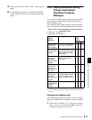
g Setting change and adjustment progress message
display area
For details, see 7-2-3 “Display Modes and Setting Change
Confirmation/Adjustment Progress Messages” on page
115.
h Operation/error message display area
For details, see “Operation/error messages” on page 169.
PDW-530 #30001
EM
D5600
16:9
IMX50
6, qj, qk, ql and wa appear only when color bars are displayed.