


Chapter 1 Overview
16
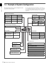
1-2 Example of System Configuration
1-2 Example of System Configuration
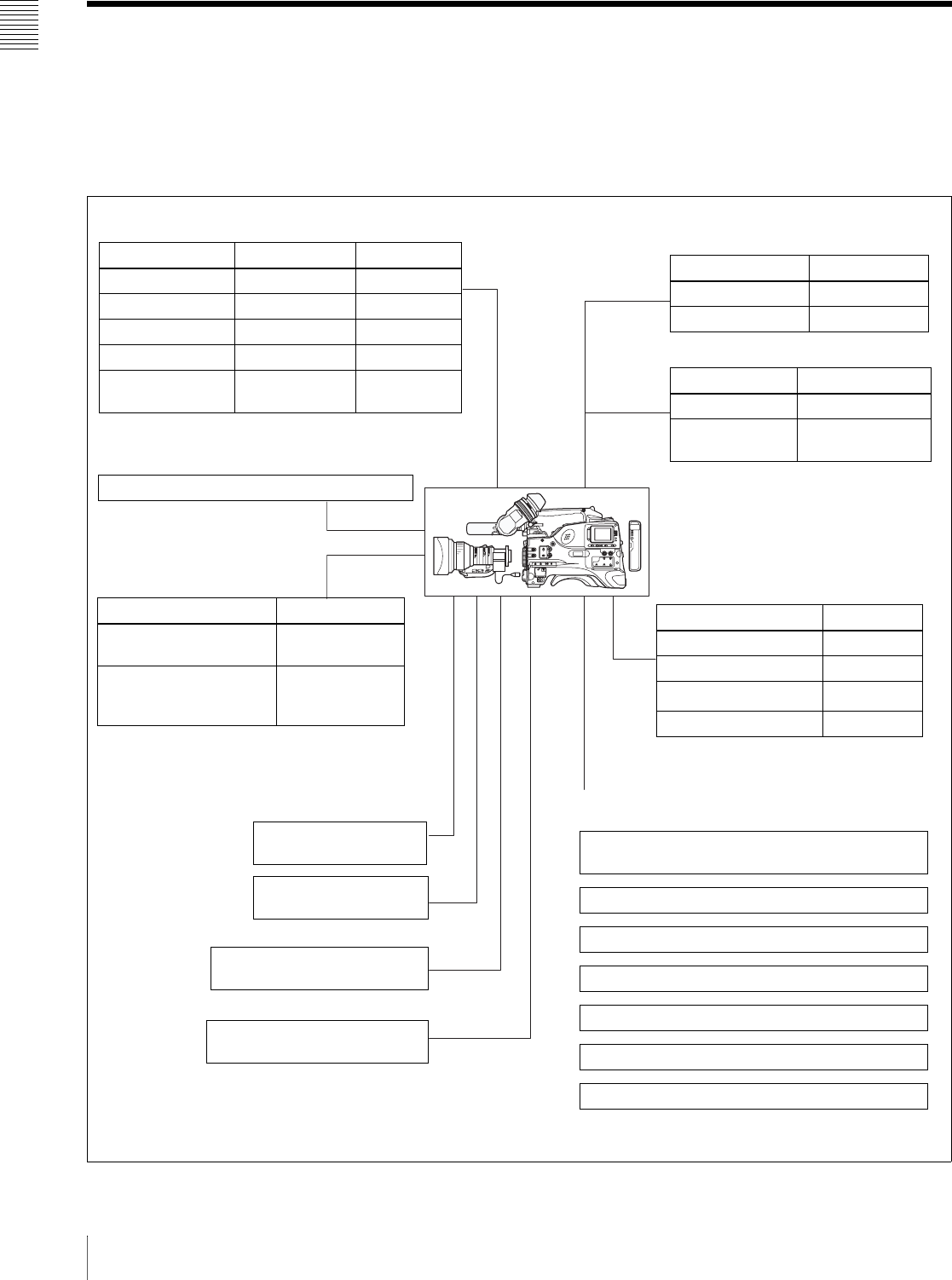
The diagram below shows a typical configuration of the
camcorder for ENG and EFP.
For more information about the fittings, connections, or
use of additional equipment and accessories, see Chapter
9 as well as the operation manuals for the connected
equipment.
“Memory Stick”
(see page 198.)
RM-B150/B750 Remote
Control Unit
Video monitor for color image
check during shooting
Extension board
2) For PDW-510/530 only
Product Model name
SDI Output Board CBK-SD01
Composite Input Board CBK-SC01
Pull Down Board
CBK-FC01
2)
Network Adaptor CBK-NC01
Viewfinder-related equipment
Name / Purpose Magnification Part No.
Fog-proof filter – 1-547-341-11
Lens assembly –2.8 D to +2.0 D A-8262-537-A
Lens assembly –3.6 D to –0.8 D A-8262-538-A
Lens assembly –3.6 D to +0.4 D A-8267-737-A
Lens assembly
(3 × magnification)
–2.4 D to +0.5 D A-8314-798-A
AC power supply
Battery
1) BP-L40/M50 cannot be used.
Product Model name
AC Adaptor AC-550/550CE
AC Adaptor AC-DN10
Product Model name
Battery Charger BC-M150/M50
Battery Pack
1)
BP-GL65/GL95/
L60S/M100
Camera adaptor
Product Model name
Input of audio channels
3/4 and SDI output
CA-701
CCZ (26-pin) output/
analog composite/SDI
input
CA-702/702P
Connection through i.LINK interface
Devices with a DV connector (DSR-DU1 etc.)
Audio signal source
External microphone ECM-672 or similar
microphone
CAC-12 Microphone Holder
Audio equipment
WRR-862 UHF Portable Tuner
WRR-855 series UHF Synthesized Tuner Unit
CCXA-53 audio cable
DMX-P01 Portable Digital Mixer
XLR 5-pin connector for stereo
microphone (service part)