


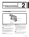

Chapter 2 Locations and Functions of Parts and Controls
23
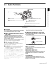
2-3 Audio Functions
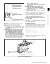
j AUDIO SELECT CH-1/CH-2 (audio channel-1
and channel-2 adjustment method selection)
switches
These switches select the audio level adjustment method
for each of audio channels 1 and 2.
AUTO: Select this setting for automatic adjustment.
MANUAL: Select this setting for manual adjustment.
k AUDIO IN CH-1/CH-2 / CH-3/CH-4 (audio input
selection) switches
AUDIO IN CH-1/CH-2 switches
These switches select the audio input signals to be
recorded on audio channels 1 and 2.
FRONT: The input signal source is the microphone
connected to the MIC IN connector.
REAR: The input signal source is the audio equipment
connected to the AUDIO IN CH1/CH2 connectors.
WIRELESS: The input signal source is a WRR-855A/
855B UHF Synthesized Tuner Unit (option).
AUDIO IN CH-3/CH-4 switches
These switches select the audio input signals to be
recorded on audio channels 3 and 4.
F (front): The input signal source is the microphone
connected to the MIC IN connector.
R (rear): The input signal source is the audio equipment
connected to the AUDIO IN CH1/CH2 connectors.
W (wireless): The input signal source is a WRR-855A/
855B UHF Synthesized Tuner Unit.
With a CA-701 Camera Adaptor (option) connected to the
camcorder, you can record separate sounds on audio
channels 3 and 4.
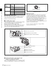
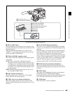
l LINE /AES/EBU / MIC selectors
These select the audio source of the audio input signals
input to the AUDIO IN CH1/CH2 connectors.
LINE: Line input audio equipment
AES/EBU: AES/EBU format audio signal
MIC: Microphone input
Note
When these switches are in the MIC position, and the
+48V switch described below is on, if you inadvertently
connect any audio device other than a microphone to the
AUDIO IN CH1/CH2 connectors, the device may be
damaged.
m +48V/OFF switches
Select either of the following positions for the
microphones to be connected.
+48V: For a microphone to use an external power supply
OFF: For a microphone to use an internal power supply
n AUDIO OUT (audio output) connector (XLR type,
5-pin, male)
This connector outputs the audio signals recorded on audio
channels 1 and 2 or audio channels 3 and 4.
The MONITOR CH-1/2 / CH-3/4 switches allow you to
select the audio signal to be monitored.
o AUDIO IN CH1/CH2 (audio channel-1 and
channel-2 input) connectors (XLR type, 3-pin,
female)
These are audio input connectors for channels 1 and 2 to
which you can connect audio equipment or a microphone.
When the LINE / AES/EBU / MIC selector is set to AES/
EBU, the CH1 connector is used for channel-1 and -2
inputs, and the CH2 connector, for channel-3 and -4 inputs.
p DC OUT 12 V (DC power output) connector (4-pin,
female)
This connector supplies power for a WRR-862 UHF
Portable Tuner (option). Do not connect any equipment
other than the UHF portable tuner.