


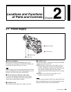
Chapter 2 Locations and Functions of Parts and Controls
27
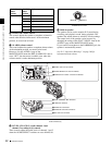
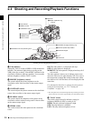
2-4 Shooting and Recording/Playback Functions
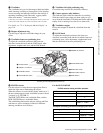
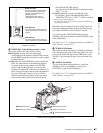
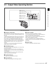
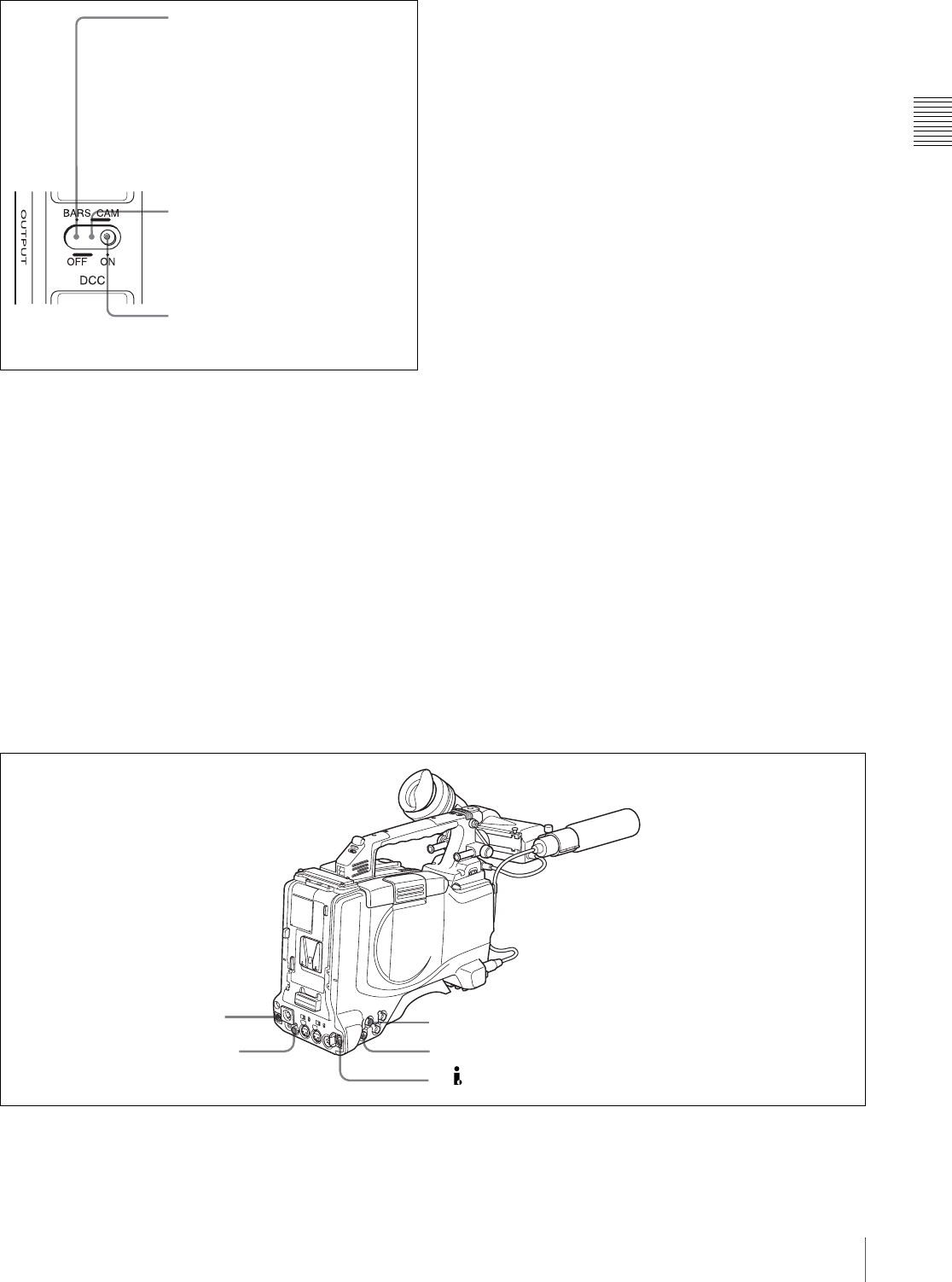
OUTPUT/DCC selector
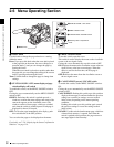
t WHITE BAL (white balance memory) switch
This switch controls the white balance setting.
PRST (preset): Adjusts the color temperature
corresponding to the position of the FILTER selector.
Use the PRST setting when you have no time to adjust
the white balance.
A or B: When the AUTO W/B BAL switch is pushed to
WHT, the white balance is automatically adjusted
according to the current position of the FILTER
selector, and the adjusted value is stored in either
memory A or memory B. (There are two memories for
each CC filter, allowing a total of eight adjustments to
be stored.) When this switch is set to A or B, the
camcorder automatically adjusts itself to the stored
value corresponding to the current settings of this
switch and the FILTER selector.
You can use the AUTO W/B BAL switch even when
ATW
1)
is in use.
B (ATW): When this switch is set to B and on the
FUNCTION 2 page of the OPERATION menu,
“WHITE B CH” is set to “ATW”
1)
, ATW is activated.
1) ATW (Auto Tracing White Balance)
The white balance of the picture being shot is adjusted automatically for
varying lighting conditions.
When this switch is adjusted, the new setting appears on
the setting change/adjustment progress message display
area of the viewfinder screen for about 3 seconds.
You can assign the ATW ON/OFF function to the
ASSIGN 1 switch (push button) on the FUNCTION 1 page
of the USER menu.
For details, see 7-3-5 “Assigning Functions to ASSIGN 1/
2/3/4 Switches” on page 125.
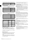
u TURBO GAIN button
When shooting under extremely poor lighting conditions,
press the button once to boost the video gain to the value
preset on the GAIN SW page of the USER menu (up to
48 dB). To stop boosting the gain, press the button once
more.
v ASSIGN 3/4 switches
You can assign the desired functions to each of the
ASSIGN 3 switch and ASSIGN 4 switch on the
FUNCTION 1 page of the USER menu.
For details, see 7-3-5 “Assigning Functions to ASSIGN 1/
2/3/4 Switches” on page 125.
Shooting and recording/playback functions (3)
BARS, DCC OFF
A color bar signal is output and the
DCC circuit does not operate. For
example, use the setting for the
following purposes.
• Adjusting the video monitor
• Recording the color bar signal
CAM, DCC OFF
The video signal from the camera is
output, and the DCC circuit does not
operate.
CAM, DCC ON
The video signal from the camera is
output, and the DCC circuit operates.
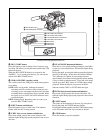
wf REMOTE connector
wd VIDEO OUT connector
wg GENLOCK IN connector
wh TEST OUT connector
wj DV IN/OUT S400 connector