


Chapter 2 Locations and Functions of Parts and Controls
28
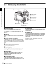
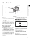
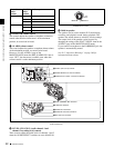
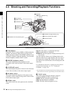
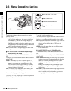
2-4 Shooting and Recording/Playback Functions
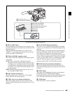
w VIDEO OUT connector (BNC type)
This connector outputs a composite video signal for a
video monitor. With a video monitor connected to this
connector, you can monitor the picture being shot by the
camera or the picture played back by the VDR. To choose
between the composite video signal output and SDI signal
output, use the menu. When synchronizing the time code
of an external VDR with that of the camcorder, connect
this connector to the GENLOCK IN connector of the
external VDR.
By installing the CBK-SD01 extension board (not
supplied), you can output an SDI signal (supporting
embedded audio and the EDH function) from this
connector.
For details on how to select the output signal, see 7-3-2
“Selecting the Output Signals” on page 122.
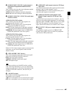
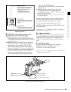
x REMOTE connector (8-pin)
Connect the RM-B150/B750 Remote Control Unit, which
makes it possible to control the VDR and camera remotely.
y GENLOCK IN connector (BNC type)
• This connector inputs a reference signal when the
camera is to be genlocked or when time code is to be
synchronized with external equipment. Use the
MAINTENANCE menu to adjust the genlock H-phase
(phase of horizontal sync signal) and the sub-carrier
phase.
For details, refer to the Maintenance Manual.
• This connector also inputs a return video signal. You can
display the return video signal in the viewfinder screen
while holding the RET button down with “RETURN
VIDEO” set to “ON” on the GENLOCK page of the
OPERATION menu.
• This connector also inputs an external analog composite
video signal.
When the CBK-SC01 extension board is installed, you
can record the external analog composite video signal
input to this connector.
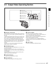
z TEST OUT connector (BNC type)
This connector outputs the video signal for a video
monitor. The output signal can be selected from composite
or RGB. The factory setting is composite, and the setting
returns to composite whenever the unit is powered on.
Depending on internal board and menu settings, menus,
time code, and shot data can be superimposed on the image
on the monitor. Like the VIDEO OUT connector, this
connector can also be used to synchronize the time code of
an external VTR with the time code of the camcorder.
For details on how to select the test output signal, refer to
the Maintenance Manual.
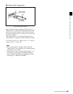
wj (i.LINK) DV IN/OUT S400 connector (6-pin,
IEEE1394 compliant)
Connect to a device supporting the DV format or a
computer, using a i.LINK cable.
Notes
• If video and audio signals are not output to an external
device connected to the i.LINK DV IN/OUT S400
connector, try disconnecting the i.LINK cable and then
reconnecting it, making sure that it is firmly seated.
• When you connect this unit to an external device with a
6-pin i.LINK connector, always power this unit off and
disconnect the DC cable from the DC IN connector, or
remove the battery pack, before connecting or
disconnecting the i.LINK cable.
If you connect or disconnect the i.LINK cable while
power is being supplied to this unit, high voltage (8 to 40
V) can flow into this unit from the i.LINK connector of
the connected equipment, possibly damaging this unit.
• When you connect this unit to an external device with a
6-pin i.LINK connector, always connect the 6-pin
i.LINK connector on the external device first.